Neil's blog
Using freeradius to assign vlans for unifi wi-fi.
This is another post which is as much for me as for anyone else.
I have a UniFi-based Wi-Fi setup, with different VLANs for different things. The UniFi controller is running on a Debian 10 virtual machine.
Rather than just using different SSIDs for each VLAN, I wanted one VLAN, and then to use radius to authenticate users, and assign them to the right VLAN.
I was planning on using a bit of Ubiquiti hardware for this - one of their Unifi Security Gateways - but I wanted to use it only for the radius functionality, and not for any routing. However, according to the UniFi support, this is not possible (yet, at least).
So I am using freeradius, running on the same virtual machine as the UniFi controller.

Getting freeradius working
Installing freeradius should be as simple as
And it might be for you.
I had a bit of a fight with it, and I’m not 100% sure if it is my fault (probably), or some unusual packaging issue.
My problem was perhaps an edge case - I have tried this before, gave up, and seemingly deleted the directory structure in /etc/freeradius. When I tried to re-install freeradius with apt install freeradius -y , it failed, citing the lack of /etc/freeradius.
The solution - thanks to 0x47DF - was that I had seemingly failed to purge all the various freeradius apt packages.
I cannot be sure exactly what I did to get it working, as I tried so much, but I think it was:
Anyway, I finally got it running.
Configuring freeradius
I kept configuration very light.
If you use the default Debian packages, the install path for the config files is /etc/freeradius/3.0 .
If you use the networkradius Debian packages, as I ended up doing, the install path for the config files is /etc/freeradius .
In mods-enabled/eap , I set the following:
- default_eap_type = tls
- use_tunneled_reply = yes in both places that stanza appeared
I left the certificates alone, as they worked. However, the default expiry is just 60 days. I have changed the config file to extend this, but I could not work out how to replace the already-generated certificates, so that is a problem for another day.
Adding a client
I am using the UniFi controller to control my system, and so I need the radius system to respond to traffic from my access points. For this, I configured the clients.conf file.
I added a new section:
Adding users
In used the users file to specify which users should get access, and to which VLAN they should be assigned.
Each user looks a bit like this:
So if you wanted to add a configuration for the username “bob”, with a password of “television-adventurer-40”, putting their traffic onto VLAN 20, you would use:
Restart freeradius
When you’ve done with the configuration, restart freeradius.
You could use systemd for that:
But it might be easier, for debugging, to start it manually:
Testing using radtest
Before trying it out on a proper device, I tested my config using radtest .
However, I could not test my unifi client config, only the default config for localhost.
For the “bob” user above, you might test it with:
You should get a result of:
Connecting the UniFi controller to radius
The UniFi side of things was quite easy.
In Settings / Profiles (in the Unifi controller), I created a new radius profile.
I ticked Enable RADIUS assigned VLAN for wireless network .
For IP address, I gave:
- IP address: the IPv4 address of the server (not localhost / 127.0.0.1)
- Password: the “secret” I set in the unifi section of freeradius’s client.conf
I saved the profile.
Also in Settings, in Wireless Networks, I created a new wireless network, set the RADIUS profile to the profile I just created, and saved it.
Connecting a device
On my device - in my case, an Apple TV - I selected the SSID, and was prompted for the username and password. I used the credentials I set up in the freeradius users file. I was then prompted to accept the unsigned, soon-to-expire, certificate.
And it worked: the Apple TV was assigned to the right VLAN.
If that works, it should be straightforward to attempt to connect
Get Mozilla Firefox
Managing VLANs on a RADIUS NPS Server with UniFi Access Points
- Last updated: Aug 15, 2023
I have elegantly demonstrated how to set up a WPA Enterprise architecture using PEAP-MSCHAPv2 🤢 and EAP-TLS 🥰. The configuration works seamlessly. However, in my network, there are different user profiles for Wi-Fi access, each requiring access to specific VLANs . So, how can we ensure that certain users are directed to the ADMINS VLAN, while others are assigned to the USERS VLAN?
There are two strategies to achieve this: the first involves multiple SSID configurations (one for each VLAN), requiring a separate RADIUS server for each VLAN management. However, this approach can become complex and unwieldy. The more efficient solution is to leverage RADIUS attributes such as Tunnel-Private-Group-ID , Tunnel Medium Type , and Tunnel Type to enable dynamic VLAN assignment . By doing so, we can manage all the VLANs from a single NPS server, and users will only need to connect to a single SSID . In this guide, we will delve into this latter method.
- We have successfully configured either a functional PEAP-MSCHAPv2 or EAP-TLS setup.
- The VLANs have been properly established within our network.

UniFi Network Server
We need to configure several settings within the UniFi Network Server . Let's take a closer look at the process.
In this scenario, let's consider a setup with three distinct networks: 192.168.1.0/24 designated for Servers and WiFi access points , 192.168.10.0/24 allocated for Users , and 192.168.100.0/24 specifically reserved for Administrators .
- Within the RADIUS profile, activate RADIUS Assigned VLAN Support for Wireless Networks :

- Ensure that your VLANs are accurately configured:

Authentication Server (NPS)
- Open the Network Policy Server Console:

You should establish two separate Network Policies : one dedicated to the ADMINS and another for the USERS .
- Click New in the Network Policies folder:

- Give a name to the Policy :

- Click Add to specify the condition:

- Select User Groups , and click Add Groups… :

- Add an Active Directory group of users, such as Domain Admins for ADMINS :

- Click Next :

- Select Access granted :

- In the Configure Settings section, you can eliminate the pre-existing entry for Framed-Protocol PPP and then proceed to click on Add… :

- Tunnel-Type : Virtual LANs (VLAN)
- Tunnel-Pvt-Group-ID : Set to 100 for ADMINS or 10 for USERS
- Tunnel-Medium-Type : 802 (including all 802 media along with Ethernet canonical format)
- Add Tunnel-Type parameter:

- Add Tunnel-Pvt-Group-ID parameter:

- Add Tunnel-Medium-Type parameter:

- Once you have entered all the parameters, proceed by clicking Next… :

- Lastly, click Finish to finalize the creation of the Policy :

- Now, you just need to repeat the same process for the USERS VLANs, and you're done!
How to Setup and Secure UniFi VLAN
When you have a UniFi Security Gateway or UniFi Dream Machine (UDM, UDM Pro) you can create different VLANs on your network. Virtual LANs (VLANs), allow you to divide your physical network into virtual networks, offering isolation, security, and scalability.
Now you might think, do I really need VLANs? But when guests are connecting to your home network, you probably don’t want them to have access to all your network devices. And if you have a smart home, then creating a separate VLAN might be a good idea. Because the security of IoT devices is not always as it should be.
In this article
So in this article, I will explain how to set up and secure VLANs in the UniFi Network Console.
Note This article is updated in April 2024, using the latest UniFi Network version (8.1.x). It now include the new Traffic Rule and Firewall rule screens.
Setup UniFi VLANs
Creating VLANs in UniFi exists out of a couple of steps because we not only have to create the different networks, but we also need to secure the VLANs. The “problem” with UniFi is that inter-VLAN traffic is allowed by default. So without any firewall rules, traffic from for example the guest VLAN can just access the main VLAN.
In this example, we will be creating 3 VLAN networks for:
- Guests – VLAN 20
- Cameras – VLAN 30
- IoT devices – VLAN 40
The guest VLAN is a bit different from the other VLANs because UniFi will automatically create the necessary firewall rules for the guest network. All you have to do is Isolate the network in the network settings.
So in the steps below, we will create the guest network, with the correct settings, but further on I will use the IoT VLAN as an example.
Step 1 – Create the UniFi VLAN Networks
The first step is to create the different networks for the VLANs. I have used custom VLAN IDs in the steps below, but you can also leave Auto Scale Network on. This way UniFi will automatically create the IP Range and VLAN ID.
Open your UniFi network console and navigate to:
- Settings > Networks
- Click on New Virtual Network
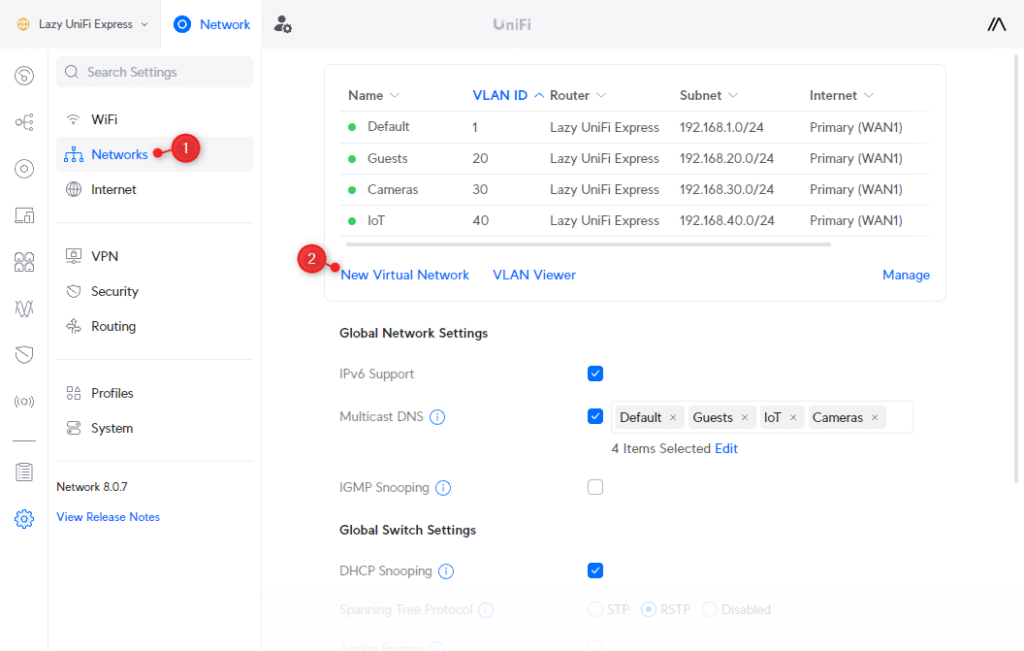
We are first going to create the guest network:
- Enter Guests at the Network Name
- Deselect Auto-Scale Network
- Set the host address to 192.168.20.1
- Change Advanced Configuration to Manual
- Change the VLAN ID to 20 so it matches the IP range
- Enable Isolation by checking Network
- Change the Content Filtering to Family (optional)
- Click Apply Changes

Next, we need to create the network for the Cameras and IoT devices. Click again on New Virtual network , and repeat the steps below for both Cameras and IoT , using VLAN 30 for cameras and 40 for IoT:
- Network Name: IoT
- Disable Auto Scale Network
- Host Address: 192.168.40.1
- Advanced Configuration: Manual
- VLAN ID: 40
- Isolation: Off
- Click Apply Changes (and repeat for cameras)

Using VLAN Magic
If you are running UniFi Network 8.0.24 or higher, then you can also use the new VLAN Magic feature to create virtual networks. It allows you to create a new virtual network from the device overview, and simply assign devices to the VLAN by selecting them.
UniFi Network will then use the virtual network override feature to move the device to the assigned VLAN. The advantage of this method is that you don’t need to create wireless networks for your VLANs, but when applying this on a wired device, you will need to make sure that your ports are configured correctly (I will explain that later in the article).

To create a new VLAN with VLAN Magic:
- Open the Topology view
- Click on the plus icon the create a new VLAN
- Select the devices in the overview to assign them
- Click on Apply Changes
Step 2 – Block traffic between VLANs
With the networks and VLANs created, we need to block the traffic between them. By default, devices in, for example, the IoT VLAN, can access the device in your main VLAN. Guests however are already isolated by the automatically generated firewall rules by the Isolated Network option.
There are two options to block inter-VLAN traffic, we can create custom firewall rules, or use a Traffic Rule. The latter is a lot quicker to create, but I will explain both methods.
Note During my tests, it took a couple of minutes until a traffic rule was effective. So after creating a rule, give it a couple of minutes before you test it out.
Using Traffic Rules
Ubiquiti is really promoting the use of Traffic Rules to block or allow traffic on your network. In the last update, they merged the Traffic Rules and Firewall rules into one screen. You can now create two rule types: Simple and Advanced . Simple is the “old” Traffic Rule, and Advanced is the Firewall rule.
- Click on Security
- Choose Traffic & Firewall Rules
- Click on Create Entry
- Make sure Simple is selected as Rule type

When creating Traffic rules, make sure that you have set the Rule Type to simple.
- Rule type: Simple
- Name: Block Inter-VLAN
- Action: Block
- Source: All Devices
- Destination: All Local Networks
- Traffic Direction: Traffic from all local networks
- Schedule: Always

You probably want to access your IoT device, for example, from your main (default) VLAN. To do this we can create another Traffic Rule to allow traffic from the Default network to the IoT network. Now this is where Traffic Rules become a bit confusing for most, let’s first create the rule and I will then explain it a bit:
In the Traffic Rules click on Create Entry :
- Name: Allow Default to Access IoT Devices
- Action: Allow
- Source: Default
- Destination: Local Network Select: Iot
- Traffic Direction: Traffic to all networks

So what we have done here, is Allow all traffic from the Default network (Device/Network) to a local network, in this case IoT. The Traffic Direction is set to Traffic to all local network, which means that traffic initiated from the default network is allowed, but traffic initiated from the IoT network not.
I have only selected IoT here as the local network, but you can also select the other VLANs you want to have access to from your default network.
Using Firewall Rules
We can also block the inter-VLAN traffic with custom firewall rules. This is however a bit more work compared to the Traffic Rules.
Before we can block the inter-VLAN traffic, we first need to create 3 other rules:
- Allow established and related connections
- Drop invalid state connections
- Allow the main VLAN to access all VLANs
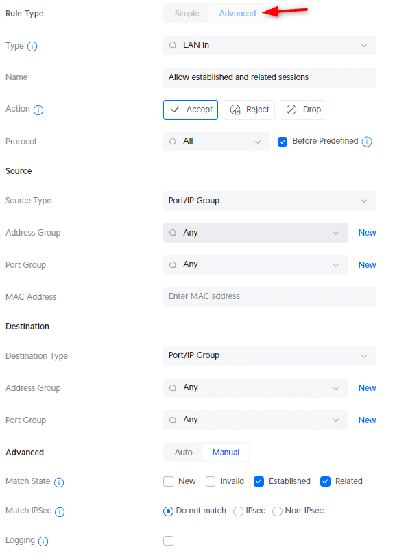
To create a new Firewall rule, we create a new entry in the Traffic & Firewall Rules. But make sure that you set the type to Advanced in the new rule.
- Click on Create New Rule

We are first going to create the rule that allows all established and related sessions.
- Rule Type: Advanced
- Type: LAN in
- Description : Allow established and related sessions
- Action: Accept
- Source Type: Port/IP Group
- IPv4 Address Group: Any
- Port Group: Any
- Destination Type: Port/IP Group
- Under Advanced: select Match State Established and Match State Related
- Apply Changes
The second rule that we are going to create is to drop all invalid states:
- Description : Drop invalid state
- Action: Drop
- Under Advanced: select Match State Invalid

And the third rule that we need to add is to allow traffic from our main VLAN to the other VLAN. This way we will be able to manage all the devices even if they are in IoT VLAN for example.
To create this rule we will first need to define an IP Group. Port/Ip Groups allow you to easily apply a rule to multiple port numbers or IP ranges. In this case, we want to match the IP ranges of all VLANs.
- In the settings menu, click on Profiles
- Scroll down and click Create New under IP Groups
- Profile name: All Private IPs
- Type: IPv4 Address/Subnet
- Address: 192.168.0.0/16 (this will match all addresses that start with 192.168.x.x)

With the IP group created, go back to Traffic & Firewall Rules and create the following rule:
- Description : Allow main VLAN access to all VLAN
- Source Type: Network
- Network: Default
- Network Type: IPv4 Subnet
- IPv4 Address Group: All Private IPs (the IP Group that we just created

We can now create the rule that will block traffic between the VLANs. The rules that we just created will ensure that we can still access the devices in the other VLANs from the main VLAN. For this rule, we are also going to use the IP Group that we created earlier.
Click on Create New Rule in Traffic & Firewall Rules and add the following rule:
- Description : Block VLAN to VLAN
- IPv4 Address Group: All Private IPs

We now have separated the VLANs in our UniFi network, preventing unwanted inter-VLAN traffic.
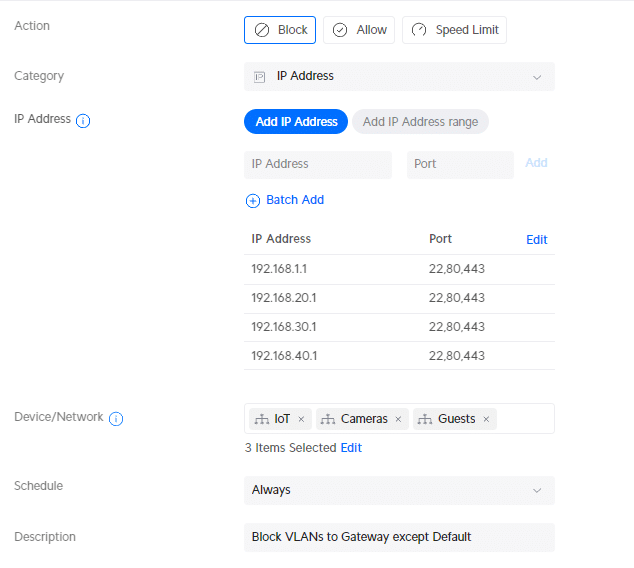
Step 3 – Block Access to Unifi Network Console from VLANs
Devices in your VLAN will need to have access to your network console (UDM Pro for example). But what we don’t want is that users (guests or IoT devices) are able to access the interface of our UniFi network console.
What we also want to prevent is that devices from IoT can access the gateway of the main VLAN.
Now this is something that should be possible with a Traffic Rule in my opinion, but honestly, I can’t get it to work. I am still waiting for an answer about this from Ubiquiti. I created the following rule, if anybody knows why this isn’t working, please drop a comment below:
- Category: IP Address
- 192.168.1.1 – Port 22,80,443
- 192.168.20.1 – Port 22,80,443
- 192.168.30.1 – Port 22,80,443
- 192.168.40.1 – Port 22,80,443
- Device/Network: IoT, Cameras, Guests
- Description: Block VLANs to Gateway except Default
So for now, we will create a firewall rule for this. First, we need to create a couple of Port and IP Groups. Open the Profiles in the settings menu and click on Create New Group under Port and IP Groups . Create the following IP Groups:
The last Port Group that we need to create is to block only HTTP, HTTPS, and SSH access to the UniFi Network Console. The device will need to be able to access the gateway, but as mentioned, we don’t want to expose the console self.
- Profile Name: http,https,ssh
- Type: Port Group
- Port: 80, 443, 22

Next, we are going to add the firewall rules. This time we will be using the type LAN Local
- Type: LAN local
- Description : Block IoT to Gateways
- Network: IoT
- IPv4 Address Group: Block IoT to Gateways

And the rule to block access to the UDM Console. Note that we will be using the Port Group http,https,ssh here that we created earlier!
- Description : Block IoT to UDM Interface
- IPv4 Address Group: Block IoT Gateway Interface
- Port Group: http,https,ssh

Repeat the steps above but this time for the Cameras VLAN.
Assign devices to VLANs in UniFi Network
We have created all necessary rules to block inter-VLAN traffic, so all we need to do now is assign our devices to the correct VLAN in UniFi Network. For wired devices, we can assign a network to the port on the switch. And for the wireless devices, we will need to create a separate SSID.
Assign VLAN to Switch Port
By default, each switch port allows all tagged VLAN traffic. This means that if the connected device has the correct VLAN ID configured, it can access that VLAN. Which for most situations. It also allows access points or switches to pass through traffic from all VLANs if needed.
But when we have a network camera or smart home device connected to a switch, then we want to only allow access to the corresponding VLAN. The device should not be able to access any other VLAN (by changing its VLAN ID for example).
To do this, we will need to configure the Native VLAN on the port and block all tagged VLAN traffic.
In the UniFi Network console , open the new Port Manager and select your Switch . We are going to use the new Ports Manager because this will give you a create overview of all your switch ports and VLANs.
Tip By default, you can select and change multiple ports by just selecting them one after another. Mind this when you want to change another port.
- Open the Port Manager
- Select the Switch
- Select a port of a camera or smart home device
- Change the Native VLAN to the correct Network (VLAN)
- Change Tagged VLAN Management to Block All
- Reboot your Camera by Power Cycle the port

Change the other ports as well, assign them to the main VLAN by selecting the Port Profile LAN or another appropriate Port Profile.
Make sure that you Allow All Tagged VLAN traffic on the Uplink port (recognized by the up arrow ^) and the access points port
Assign VLAN to Wireless Devices
If you have a UniFi doorbell, for example, you might also want to assign this device to the camera’s VLAN. The problem is that we can’t set a VLAN on the doorbell itself. The same problem occurs with a lot of IoT devices, on most, you can’t configure a VLAN ID.
So the only option is to create a separate SSID (wireless network) for each VLAN and assign the wireless network to the correct VLAN.
Note We can also use Private Pre-Shared keys for this. This way you only have one SSID, but depening on the used password, a device is assigned to a different virtual network (VLAN). But I have noticed, that not all devices seem to work well with this yet, so make sure you test it out properly.
- Open Settings and select WiFi
- Click on Create New WiFi network
- Enter a name and password for the wireless network
- Change network to the correct VLAN (IoT for example)
- Click Add WiFi network

You can change the WiFi connection of your UniFi Doorbell in the Protect Console > Devices > Settings > WiFi Connection.
Creating Firewall Exceptions
Sometimes you need to allow access between specific devices in different VLANs. In these cases, there are again two options to allow this. We can create a Traffic Rule or add a Firewall rule.
Using a Traffic Rule
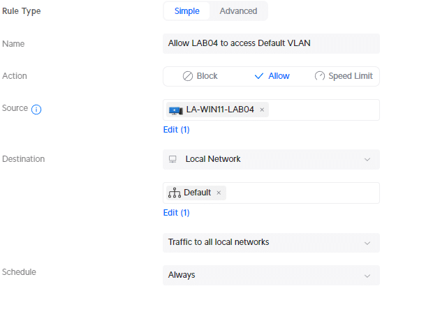
Traffic Rules are the most convenient to use for this. We can simply create a new rule where we can select the device that we want to give access to the specified VLAN. For example, to give the LAB01 notebook access to the Default VLAN, we can create the following traffic rule:
- Source: <select-device>
- Destination: Local Network
- Select network: Default
- Traffic Direction: Traffic to all local networks
Using a Firewall Rule
When using a Firewall rule, we need to create an allow rule and place the rule above the Block VLAN to VLAN rule. Let’s take the following example, allowing IoT devices to access a Raspberry PI in the main VLAN.
When you create an allow rule, try to be as specific as possible. If it’s only between two devices, then use the IP Address of both devices. If you know the protocol, then specify the port number as well.
Create a new firewall rule:
- Type: LAN In
- Description : IoT to Raspberry Pi
- Destination Type: IP Address
- IPv4 Address: 192.168.1.x

Next, we will need to move the rule above the Block VLAN to VLAN rule that we have created in the beginning. You can drag and drop rules using the 6 dots at the beginning of the rule:
- In the Traffic & Firewall Rules select Advanced
- Choose LAN In
- Drag the new rule above the Block VLAN to VLAN (Rule index 2003)

Wrapping Up
VLANs allow you to secure your local network by making sure that devices from one VLAN can’t access the other. Because inter-VLAN access is by default allowed in UniFi, we will need to create quite an amount of rules before we can safely use it.
I hope this article helped you to set up UniFi Vlans. If you have any questions, just drop a comment below.
You may also like the following articles

New UniFi Gateway Max Released

UniFi G5 Turret Ultra Review
UniFi Protect 3.0.x Update
197 thoughts on “how to setup and secure unifi vlan”.
Hello Rudy, great article that I used to implement firewall rules on my VLANs. Your setup allowed me to understand that many devices, in particular Amazon’s ones (EchoDot/Flex…) are trying to access to gateways and are blocked by your rule “Block IoT to Gateways”. At the same time I had some issues with MSFT Teams web meeting and I related that to the “drop invalid state” rule. The rule was dropping the connection to MSFT servers generating issues and pausing it the problem disappeared. Do you have any insight for this? I see that the same rule is dropping also other connections to servers like Amazon. Thanks a lot
That is quite strange. Drop invalid state blocks incoming traffic that is not new, related or belongs to established flow. So it should not cause any issues and is something you should implement.
I have the rules just like in the article, and haven’t had any issues with Teams.
I found the “bug”. Reviewing the entire config I realized that I forgot the default network gateway in two profiles (IoT and Security to Gateways). I added it and I have no more drops. Still have some devices (Apple, SKY, AMZN Echo) dropped when they are trying to reach Amazon (mainly) or other servers and still have some blocked access to gateways (mainly AMZN echo devices but also Roomba) but I think that this is “normal”.
Yes, I too see dropped packets for Amazon and weird pings from the Echos to random addresses. The Trigger log is full of ‘Alexz – xxx’ (I named them by location in the house) was blocked from accessing something on my core LAN by firewall rule or from accessing something on the internet from Drop Invalid States. I can’t tell any difference in my devices themselves at the moment.
Thank you for the great walk-through guides! They’re really helpful. Do you have any experience of configuring AirPlay-devices through different VLANs? I’ve been trying to setup my AirPlay-devices in a guest-network. I’m aiming at securing my default network from temporary devices(e.g. friends visiting), but still making it possible for my friends to access my AirPlay-devices. So far I’ve only been able to see a speaker connected to other VLAN, but when connecting to it, it doesn’t play. Firewall port issue? Any tip is appreciated!
But what happens if you create a traffic rule to allow the airplay device (based on IP Address) to allow traffic from and to the default VLAN?
Trying to setup the firewall rules i do not see the local network under destination. The only option are app, app group, domain name , IP address, region
It’s a bit unclear in the UniFi interface, but you can scroll down in the dropdown box.
Step 3 worked for me. I’m running latest versions as of this date.
Hello. Thx for this supernice guide. Im verry noob at this but I meet a problem. Im using home assistant. What WLAN is best for that? Separate VLAN or is it ok with IoT? Currently Im havin it on default but I cant controll anything from HA cuz of the rules. When I pause “Block Inter-VLAN” then it works. The real reason why I would like to avoid to move Home Assistant to IoT VLAN is cuz I have to change IP adress of HA and I think that will give me new problems :’)
You can create a traffic rule to allow devices from the IoT to access the Home Assistant . The the direction to To and From all local networks
Great article! i think the clearest I have found around so far. I used parts of it to separate my camera vlan from the other internal devices in my home. I pulled the camera from the cable attached a laptop and indeed everything is blocked! next challenge now is when i reattach the camera, everything remains blocked so also the camera. I have searched for the port to reset. or to delete the block on the port, but so far no succes. Is there something there or do I need to reset the camera to fact def? It seems the port needs to be reset. Other angle would be to remove the rules and reapply them once everything is attached.
You could simply pause the rules and try if that helps. Or just power-cycle the port
Tried all of that, no succes. Finally reset the camera to fact default, moved it to another port, applies default network. Wait for it to come online, updated. then applied vlan to the new port. Lastly after everything settled, unpaused the rules. Everything is fine, but still feels a bit strange as the camera device should be known to the switch (USW 8 port pro). or is it that the state of the port changed then it will accept no other connections? Tried many things, applied def netw to the port, power cycled the port. the only thing now that seeems to work is to use another port on the switch. but weird, but at least the rules work and the traffic is blocked when cable is removed.
It seems that since you wrote this Ubuqiti has once again changed the screens. I can’t seem to find the Traffic Rules screen you have posted that exactly matches. Have my IoT network setup on my new Unifi Gateway Ultra with 8.1.113 installed.
Thanks for pointing out, I have updated the article.
Thanks. I like that they keep working on the software, and I was able to follow the detailed rules pictures thankfully, so all seems to be working now!
Thanks as always for posting all the stuff you do. I’ve referred to your stuff many time over the years. Would love to see anything about how possibly to get AirPlay to work across these VLANS, etc. as well so I can quit having to join my IoT network from my phone to stream to the TV. LOL But I don’t trust LG (or any TV company for that matter) to be on my regular network!
Hi. Great Article, thanks.
Followed you Article on an Installation with Unifi Cameras. Created the VLANs and Rules exactly like in your Article. But as soon as I change the Native VLAN from the Default to my Camera VLAN DHCP stops working on that Port. Also my Camera VLAN WLAN cant give out DHCP Addresses. Any Idea why that happens?
Have you enabled DHCP for the Camera network?
Good afternoon Rudy ,
In your section Assign VLAN to Wireless Devices, you are explaining that If you have a UniFi doorbell, for example, you might also want to assign this device to the camera’s VLAN. The problem is that we can’t set a VLAN on the doorbell itself. The same problem occurs with a lot of IoT devices, on most, you can’t configure a VLAN ID.
My question was why not just assign these devices to the IOT network ? That way the device would connect to the right VLAN no? For example if i set my doorbel to the Camera IP of 192.168.30.1, It would pulled an IP address from that therefore be assigned to VLAN 30. At least i think it would.
If you go to device in your UniFi network console, you can select the device > settings and then under IP Settings use the virtual network override option. This way you can assign a device to a specific virtual network.
Nice writeup. Other guides for blocking inter-vlan traffic suggest blocking RFC1918 range of IP addresses; you don’t, any particular reason for that? Thanks
I prefer to use the traffic rules, so there you don’t need to use the RFC1918 range. And when using the firewall rules, there is really now need to block traffic to subnet that you don’t use. If your network is designed on 192.168.x.x, then there is no reason to block traffic from 10.0.x.x., because that IP Range isn’t used in the network.
First off, I just want to show my appreciation and thank you for such a well written and comprehensive how-to article. I was confused about VLANs and using this article I was able to get everything setup. I followed ALL instructions and created the necessary VLAN and WiFi networks, and Traffice Rules when possible over Firewall rules. I did everything except for Step 3 “Block Access to Unifi Network Console from VLANs”. Has this issue with the traffic rule been resolved? If not, as with other commenters, I’m still confused why this is an issue. If an IoT device manages to get access to the default network gateway address of 192.168.1.1, I have a VERY strong password setup (24 characters long) and have 2FA setup, so rally what is the danger? My apologies but I’m still confused about this. Thanks !
There is indeed not a real danger from a IoT device. But in larger environments with guest networks for example, you just want to compeletly shield of the gateway. Security is all about adding layers, a strong password is one, seperating networks is another, and restricting access to a device is another.
Compare with securing an warehouse. You have a good lock on the door, so they won’t be able to enter the warehouse. But by placing a fence around the warehouse, they won’t even be able to access that door, so they can’t even try to open the lock.
Great article, thank you!
I had a comment/question about the “Assign VLAN to Wireless Devices” section.
You state: “So the only option is to create a separate SSID (wireless network) for each VLAN and assign the wireless network to the correct VLAN.”
It looks like if you go to Clients > > Settings there is an option for “Virtual Network Override” which seems to allow you to assign a VLAN to the client. Would this not be a valid alternative to having to create a separate SSID for each VLAN?
Yes, virtual network override can be used as well. Is has only be available since the last couple of months, and it’s not working with every device or console.
I’ve used this article recently to configure a small office, and it’s great. Thanks for the writeup! I have everything working smoothly, but one thing is still nagging me.
Your first step is to create a Traffic Rule to prevent Cross-VLAN traffic, which I did, and it works perfectly.
I have three VLAN’s – one secure, one for less-secure devices, and one Guest all on 3 different Networks, and 3 SSIDs. If I checked “network isolation” on Less-Secure and Guest hotspot, do I even need that traffic rule? Or would the secure VLAN still have cross traffic because you can’t check network isolation on your Default network?
And then to add onto that, should I even bother checking Network Isolation on those two? Does that rule take care of that?
Network isolation isolates the clients from each other on the same network. So yes, you should enable it on the guest network atleast. Guest isolation alone should work as well, but with VLANs you can also set differenent access restrictions on the network, like bandwidth limiting.
I think it’s “Device Isolation” that isolates clients from each other on the same network, “Network Isolation” is for cross VLAN traffic:
From Unifi: “Device Isolation blocks traffic between devices on the same Virtual Network (VLAN) whereas Network Isolation blocks IPv4 traffic between VLANs.”
So i’m assuming your Traffic Rule (block cross VLAN traffic) makes checking Network Isolation redundant? Your rule works great, so i’m assuming it’s not necessary. But Unifi does recommend using Network Isolation (vs Traffic/Firewall) if you are also using a Unifi Switch in conjunction with a Gateway.
No, in case of a guest network, you often want to isolate the guest devices from each other as well.
Never Mind, I got it to working with my allow airplay rule, and correct port numbers. it sometimes takes some minutes for unifi to understand new firewall rules.
How did you do that? I’ve been trying to make a guest network with airplay-devices included. I want to be able to access them from my default/trusted network as well.
Hello great instructions, but airplay is not working if I have my airplay devices on IOT network, is there any way to fix this, i also have mDNS on
Excellent article, many thanks. See, I was afraid of locking myself out of my router but you explained it nicely and showed how to prevent that from the very first rules.
I have a question around how to prevent anyone or anything self-assigning an IP in the default network. As the UDM resides on 192.168.1.1 I have vacated this subnet as much as possible but also run pi-hole and couple other components. I have turned off DHCP and limited the subnet to a /28 but I have a few gaps in that range. How do I block those IP’s from being used, say if I manually set my IP on a laptop – how to stop it from communicating on the network? There is no MAC address filtering on a network, that only exists in WiFi. Would I need to implement 802.1x, use traffic or firewall rules to effectively null the IP’s in 192.168.1.0/24?
I hope I am explaining this correctly.
Thank you for your time. Bruce
That is quite difficult to accomplish. I would create some Traffic rules for does specific IP addresses if it are a few.
Hi Rudy! Great guide. It brings a lot of new insights 🙂 One thing though: I’m confused as to why (part of) step 3 is necessary. When you already block VLAN to VLAN communication, doesn’t that include the .1 addresses of the other VLANs? (The block access to the console is clear to me). If that’s true, you’d only need to block HTTP(S) and SSL access to the gateway of its own VLAN.
Am I missing something here? Your solution seems (too) redundant.
Because the other subnets are also available on the same interface on the gateway. So we will need to block all IP addresses.
Great post, helped me a lote with my UDR. Any luck blocking Teleport VPN traffic from accesing the console admin or the main VLAN?
That is not possible at the moment. Is a known issue unfortunately.
Thanks for the very detailed HowTo’s, it helped me a lot improving overall security of my home network.
May I ask you your help (more an explanation actually…) on how I can achieve the following:
I kind of have the network layout setup according to you layout.
My default network is 192.168.2.0/24 and on the UDM-pro there are some more VLAN’s which are not relevant for my issue. I’ve setup a L2TP siste-to-site VPN server (192.168.60.0/24) to let some remote Synology NAS systems “call home”.
The clients are able to connect but it basically stops there. The remote clients are able to ping to the UDM-pro. The UDM-pro is also able to ping to the remote client and I can SSH into them, that part is fine.
However, when I try to ping from my default network (a W11 client in the 192.168.2.0/24 network) to the remote client (192.168.60.x) the requests will time out, the same happens in the other direction.
Can you point me in the right direction on how to resolve this?
Thanks in advance!
Most likely you drop all traffic coming from 192.168.60.x. Make sure that established connections are allowed.
Meanwhile I discovered that L2TP has it’s limitions on pushing routes. To make life easier I switched to the built-in OpenVPN server which pushes most part of the routes to the clients. To add missing routes you need to make some changes in the .ovpn file you can download and add them in the client config file.
Works like a charm now 🙂
To use the downloaded client configs where a Synology NAS is the client you have to remove these 3 lines:
# Downgrade privileges after initialization (non-Windows only) user nobody group nogroup
For a little more safety, change this line:
cipher AES-256-CBC
cipher AES-256-GCM
If you want a full tunnel add this in the client before the certificate part starts:
redirect-gateway def1
If you want split-tunneling don’t add that line.
If you need additional routes which aren’t pushed by the OpenVPN server running on the UDM add one or more of these lines (adapt to your needs):
route 192.168.x.0 255.255.255.0
Hi Rudy, Thanks for writing the article it’s helped a lot, but….. I don’t have a UDM, my system is based on a USG 3P and a UCK G2 Plus with a few Unifi switches and AP’s. I’m trying to connect my neighbor to my Broadband connection (he hasn’t any) using a couple of Loco M5’s in Station/AP bridge modes – that was the easy part to set up….. If I just connect the Station M5 it to my network LAN, he can see all my devices and I can see his – not a good idea!
So I’m trying to implement a separate VLAN to connect the M5 bridge to.
I’ve followed your steps and have succeeded up to a point.
If I isolate (tick the Isolation box) for his VLAN10 (192.168.10.xx) all works fine, except he can ping the USG at 192.168.10.1 – but can’t login as he hasn’t the password. So that’s OK, but as I’m on the default VLAN1 (192.168.1.xx) I can’t access the M5’s to change any settings.
So I need to implement your Step 3 – Block Access to Unifi Network Console from VLANs etc…..
But you’ve lost me I’m afraid.
Originally my Network OS was v7.xx but have upgraded to UniFi OS Version 3.2.10 which included Network OS v8.0.28. – quite an upgrade… I eventually found Traffic Rules in Security>Firewall Rules>Create Entry. but it’s not available, using the link just gives ‘UniFi is having trouble with this direction’
So I need more help with doing it using Firewall Rules please.
Thanks, Colin
Traffic rules are not supported on the USG. You will need a next-generation firewall.
Hi Ruby, Suddenly started getting updates from your LazyAdmin post – didn’t even realise my question had been posted, so thanks. I eventually sussed about the USG, so I’ve ordered a Ubiquiti Unifi Dream Machine (Special Edition) which should be with me soon. But I hoped you would explain more about ‘Step 3 – Block Access to Unifi Network Console from VLANs etc…..’ Are your instructions for Step 3 not using Traffic Rules? If so, do I start your instructions in: ‘settings/profiles/port-ip-groups/form/new’ ? Thanks,
Yes you start with creating the Port IP Group. I still can’t the traffic rule to function for this, so we stick with the firewall rule for now.
Cheers Ruby, I’ll give it a go. Colin
Brilliant articles on UDM. It’s beneficial and up-to-date!
Thanks so much. The Traffic Rule block bug still exists for Gateways 🙂
What would i need to block if i just want to block wifi on a different vlan from accessing the main network and access to the dream machine? Thx
You would need to create a separate network for that. You can’t just block all clients connected through the WiFi.
Traffic Rules are created in the LAN-IN chain and take precedence over the LAN-IN Firewall Rules. Blocking to the Gateway IP’s requires LAN-Local rules.
I suspect this is done to prevent people locking themselves out of their controllers.
Very help-full article, thanks a lot!
How to block communication between clients in a specific VLAN?
Between all clients or between specific clients? For the first you could use network isolation and for the second you will need to make sure that the clients have a fixed IP Address. Then you can make a traffic rule for it.
I do not have access from my main vlan to devices in other vlans. I paused all rules.
Does anybody know why that is so?
Did you create the traffic rule to allow access from your main VLAN? (Allow Default to Access IoT Devices)
I am having a similar problem – I have paused the firewall rules and have created the traffic rule to allow access as stated above. Any ideas?
Thank you for this tutorial and relatively up to date screenshots (Unifi keeps tweaking) to help me with my UDR.
I followed everything you did and it works beautifully! Now when I went to allow my IoT network to my Plex sever hosted on Default I ran into issues.
I tried the Firewall Rules and placed it at the top. Tried a few different iterations of this but none of them would work. I finally tried your Traffic Rules method pointed to an IP address of my server with the port and it finally worked.
Action: Allow Category: IP Address IP Address: Device/Network: IoT Schedule: Always
I used Traffic Rules to create the blocking of VLAN traffic. So I can only think that the Traffic Rules were not playing well with the Firewall Rules for allowing certain traffic through. Thought on what I did (outlined above) and thoughts of why it may not have worked with Firewall Rules?
We can see the firewall rules created by the traffic rules, so you can’t place your firewall rule above the rule created by the traffic rule. That’s why it’s probably not working.
Your traffic rule looks fine.
Thanks for the input! It’s chugging along and got my toes submerged into it.
Hello, I used your settings for VLAN blocking. However, I need advice on one thing. I have 2 houses (different VLANs) with cameras in both. Let’s say house 1, where the NVR is located, has the IP 10.30.0.1, and house 2, where the other cameras are (connected wirelessly via AP), has the IP 10.40.0.1. In house 2, VLAN 10.30.0.1 is set on the port for cameras, but the NVR in house 1 cannot see the cameras. I’m interested in how to set up a rule or firewall so that the NVR can see those cameras.
Create a seperate VLAN for the cameras and NVR, and use that in both houses. Or alternatively, create a separate VLAN for the cameras in house 2, and use a traffic rule to allow access to and from that network to the NVR
Great article! I am new to UniFi equipment and have a question about your article. Is there a way to setup a secure/isolated network for port forwarding for hosting a game server? It looks like the guest network setup may work, but I want to make sure I have any additional steps needed. Thans for any help! Happy New Year and Best Regards, Tony
Guest network could be an option, but you can also create a new VLAN for it while making sure that you created the inter-VLAN blocking rules.
Will the traffic rules allow me to access my printer on IoT network? Right now I’m not able to an upon searching lots of people have the same issue with HP printers.
If you create the allow rule for the printer, then yes it should work.
Can I ask a vlan question regarding guest networks?
Using the 8.0 unifi console I had originally created a vlan with the “isolation” option checked and then a wifi SSID as “open” with the “hotspot” option checked. This worked but required my “guests” to login to the hotspot portal to access the network. I decided I preferred an easier approach so that guests could scan a QR code to connect to the guest network.
I left the vlan with the isolation option set but change the SSID to wpa2/wpa3 and unchecked the “hotspot” option. I then created a QR code for the SSID and all works fine. But, guests then had access to my main vlan.
Lastly, I create a couple of firewall rules. 1 to drop traffic from guest->main and 1 to drop traffic from guest->iot. This seems to work in my testing but wanted to see if I am missing anything that would cause a security leak.
Any thoughts?
You will indeed need to use firewall rules or traffic rule to block inter-VLAN traffic. I just updated the article with the required Traffic Rules for this.
Thank you for the write up. It is really helpful. Unifi now tells me to user Traffic Rules instead of the firewall rules. They seem to be easy to setup. Do you think they are better and easier than the firewall setup?
Traffic rules can problably also used, but it is basically another way to great the same rules.
Hi, Rudy. On the part “Step 3 – Block Access to Unifi Network Console from VLANs”. Are there any easier ways of doing this with 10+ VLANs? I mean … Instead of two rules for each VLAN, could it be done with a more generic rule that allowed VLAN 1 to access the UDM, but everything else for everyone else is closed? Of course they would need DHCP-respons and stuff, but DNS shouldn’t be needed (I use Quad9 and so on), and definetily not https/http/ssh from any other VLAN than default. I am going to build a dormitory network with a UAP-AC-IW in each room, with it’s own VLAN on the WLAN and outgoing ports. Each room should only need itself and Internet. No need to reach anything else. It would be quite time consuming and possible forgotten if I need to rules for each VLAN created.
I haven’t found a solution yet. I though Traffic Rules would be a solution for this, but that doesn’t seem to work when it comes to blocking http(s) and ssh access to the gateway.
Thanks for the detailed write up.
I was able to get the “block UDM gateway” as a Traffic Rule by specifying the IPs using CIDR notation like this:
192.168.1.1/32:22,80,443 192.168.20.1/32:22,80,443 192.168.30.1/32:22,80,443 192.168.40.1/32:22,80,443
I think this is a good case to change the default port for access to the gateway when an http(s) ui is enabled. It would seem to me that if you block traffic on common ports per IP (80,443) you may also block services running across that port, not just access to the console itself.
In step: Assign Port Profiles to Switch Ports, it seems the Unifi menu options have changed. The Port Insights page has changed. Should we be changing the Ports Page’s Native VLAN/Network to “Cameras”per your example and have Tagged VLAN Management set as Allow All?
I have updated the article
Just wanted to share my thanks for this write-up, was easy to follow and helped me clean up a few of my newbie-mistakes in my home setup.
I cant get Printer access to work. I have my Printer on VLAN 20 my IOT VLAN I set my IP to 10.0.20.80. Im not able to ping this IP from default. I used your rule IOT to Raspberry changing it to default to 10.0.20.80. I still can not ping my HP Printer. Any help is greatly appreciated. Ive noticed a lot of people have issue with printers.
Hi, as far as I know I followed the tutorial to the letter. I have an issue with DHCP. For example my IOT network is defined to be in the range 192.168.40.6 – 254 by the DHCP settings for that network. However, when I connecf a client (like a windows pc f.i.) it does NOT get an IP address assigned. My DHCP settings are :
DHCP mode: DHCP Server DHCP Range: 192.168.40.6 – 192.168.40.254 DHCP default gateway : tries both 192.168.40.1 as well as Auto
What could possibly be wrong and what should I verify ?
Big thanks !!!!
is the PC connected to an access port on a switch set to that same vlan? are the vlans from the unifi console trunked to the switch you are connecting it to?
Hi this realy helped me. Thank you for your hard work.
Great guide, thank you !
Question … When a IOT device sits in a specific Wifi network, assigned a VLAN ID … I see it connects to the network without issues, however the IP address of that device does not show in the Unifi Client list interface ?
Great guide , much appreciated .
Can you pls expand your guide with the steps required to route VLAN traffic through the new UniFi magic VPN. I’ve 2 sites connected via Magic VPN with Cameras on each site but one NVR in a single site only. I want to use one VLAN for all the cameras and their NVR so would this be possible with the new UniFi magic VPN as it’s very easy to setup?
I would imagine that would be policy routing approach and work around for traffic in 2 layers 2 and 3 (based on my limited understanding) , will this be possible? What are the steps to implement it?
thanks for this nice guide. Finally a guide which describes all settings on the new unifi ui.
Why is it necessary to add the Rule “Block IoT to Gateways”? Why should the IOT devices be blocked from reaching its DHCP or DNS Server?
When I add the rule I’m not able to add new tuya devices.
It should be able to access the DNS and DHCP at it’s own gateway address 192.168.40.1. We only block http, https and ssh there.
Ruud, thank you, this is an excellent article!
I don’t quiet understand two things, only concerning the “Block traffic between VLANS”: – Allow established and related connections – Drop invalid state connections – Allow the main VLAN to access all VLANs – Block VLAN to VLAN
1. For the first two rules you use as source “Any” and destination “Any”. For the fourth rule you use as source “All Private IPs” and destination “All Private IPs”. I get the logic for the fourth rule but don’t understand why the first two rules are “Any”. Wouldn’t it be enough to just use “All Private IPs” as well?
2. I do technically understand what the second rule does “Drop invalid state connections” but I don’t understand why it’s used here? Is that just a best practice thing to do?
The first question is for understanding but the second one is if particular interest to me as I see some traffic being dropped and not sure this is right, e.g. I have Apple devices in my network and they seem to want to contact Couldflare (1.1.1.1 and 1.0.0.1) and those connections are being dropped now as invalid.
Appreciate any comments. Cheers!
1. These rules also apply to connection to the internet 2. The firewall not only blocks strange or messed-up packets but also rejects any packets that don’t belong to an ongoing conversation. Think of it like this: if you were getting a file, and the transfer finished, the connection would close. So, if the server sends more data after that, the firewall sees it as odd because there’s no active talk going on. To be safe, it’s smart to have these rules to stop any weird attempts from a compromised device.
Perfect and simple example of vlan’s setting up. I doubt about iot and video restriction access to router, this case you can’t control smart homing and NVR remotely, but it can be tuned individually. What you can advice for such trlcky task: secondary wan link (ethernet) present near usw24 (not L2) switch, connection to UDM Pro via optic. There are free ethernet ports at usw24 and at udm-pro. Is it possible to build isolated trunk between ethernet ports to path trough this wan link to udm?
hello, what about trunking? what would be the configuration for having all created vlans including the management vlan trunked out of the UDM on a single port, down range to other switches trunk ports to expand my network?
You can use the port profile all for that.
After setting up VLANs and triple checking firewall rules, I have a couple of devices in my IoT network that can only be accessed remotely or from the IoT local wifi network. Shouldn’t I be able to access them from the default local wifi network, too? Feels like I missed something.
Thanks for a great article…very helpful.
First, thank you so much for the guide.
I was wondering if you could explain a bit more on why you have LAN In for some, and LAN Local for others?
LAN In rules applies to traffic the enters the LAN from the internet. LAN Local applies to traffic that comes from within your local network.
`LAN In` is from internet? Wouldn’t that be `WAN In`? Cause all the rules in this article are `LAN …` for blocking inter VLAN traffic — nothing about internet. I’m a bit confused?
The labels are indeed confusing: LAN-IN = traffic entering the LAN interface (usually sourced from clients on the LAN, but VPN traffic is also filtered here). Also traffic from the WAN interface to the LAN interface can be filtered here. LAN-OUT = traffic leaving the LAN interface (destined for the LAN clients) WAN-IN= traffic entering the WAN interface (usually sourced from anything on the internet) WAN-OUT= traffic leaving the WAN interface
I researched some more and I think I figured it out.
Conceptually, `LAN Local` is the same as `LAN In` where `destination` is the UDM itself.
But, if traffic comes in where `destination` is the UDM itself, the UDM does not trigger `LAN In` rules. Hence why those rules need `LAN Local`.
Now I get it. Thank you!
First, thanks for the article, it’s been very helpful!
Correct me if I’m wrong, but I believe the “Block VLAN to VLAN” rule you created at or near the beginning makes blocking access to the group of gateway IP’s that are in your other VLAN’s unnecessary, as they should already be blocked, right? Thus, I think the only rule needed would be the one to block http,https,ssh to the gateway interface for said VLAN.
That is what I thought too but Unifi does not trigger the `LAN In` rules for traffic destined to the router itself. Thats why you need the other `LAN Local` rules.
Hello, I wanted to ask. If port 443 and HTTP, and HTTPS are blocked, how do you connect to the unify web interface control window? Do I need to connect directly through the computer after downloading the unifi program?
Have you installed the controller on a Windows computer? Port forwarding or a firewall execption is the best option
I am a mac os user. I haven’t installed anything on my computer yet. That’s all it takes to install the controller on the computer and I’ll be able to connect? maybe you have written somewhere in your blog about creating firewall execption rules to connect to UDM?
443 is only blocked from IoT. So devices on your main/default can still access the Unifi web interface control from your LAN.
I am thinking of upgrading the home network to something more serious. I am choosing between meraki and unifi. Do you think unifi has a good enough firewall like cisco? and I wonder if cloud key2 can be connected to cisco meraki router.? if I would like to add wifi cameras.
Thank you for you opinion
I prefer UniFi. It’s easier to set up and you don’t need monthly licenses to run and configure your hardware. The firewall of UniFi is good enough for a home or small business network. You can place the cloud key behind the Meraki router.
Thank you for your reply. I’m thinking about UDM/SE, although at the moment the internet provider only offers 1GB internet speed. Maybe in a few years there will be a higher speed. Investment in the future. I’m also thinking about acces point pro, it should probably be enough for an 88 sq m apartment.
Hey Ruud, I wanted first to say that your article was very helpful and thank you! With that, I’ve found two oddities that perhaps you could provide insight into. First, when I run an external scan of my domain (strictly housed behind the UDMP running Network 7.4.150), I find that I have a ton of ports open. I’ve confirmed that I have UPnP off, so no ports are being opened for arbitrary services. I can’t figure out why they are open.
The second is regarding securing IPv6. I’d like the same VLan structure in place, along with the firewall rules to match that coincide with the IPv4 rules and VLan’s. I currently have about 40-50 devices of various types and am trying to slowly transition to IPv6. Do you have any ideas on how to approach this, or any good references that could point me in the right direction?
And you have threat management running? I don’t have any experience with IPv6 and vLANs yet.
Oh wow, perfect article to guide a beginner like me. Many, many thanks. After setting up the groups to block port 22,80,443, I can no longer SSH to a machine on the blocked network. For now, I have excluded port 22 but would rather add a rule to allow SSH from the blocked VLAN to a specific machine on my main network. Any examples?
Thank you for year great tutorial! I have tried to implement a similar setup using USG-PRO4 and UniFi Console 7.4.150, but did find that Switch port profile configuration under which you referred to as “new Ports Insights feature” was not available. There are some other differences as well. Do you know if I should be able to set up a similar solution without a UDM? If not would you be able able to point out what I need to configure different? Thank you in advance
Great article Rudy – thankyou. I guess like many who found this article I was perplexed by the “problem” that inter-VLAN traffic is allowed by default, having set up VLANs which did “nothing”. This article has saved me hours. The rules Unifi creates with the same description are indeed “Internet In”, “Internet Local”, or “…v6…” rules and cannot be edited and the detail cannot be viewed, but I could take a reasonable guess at what they do. I read a post from Unifi that suggests they cannot be edited/viewed to “…enable the best user experience” – saving us from ourselves perhaps. UDM 7.3.83, U6-LR, u6-Lite, USW-Lite-8-poe.
I followed this tutorial and everything seems to have worked – perhaps too well. I cannot access my HDHomerun Flex 4K tuners from a different VLAN. Everything I’ve read online seems to suggest a tricky situation working with HDHR devices and VLANs. Wondering if there’s a simple way for a non-IT weekend warrior like myself.
What I hope to accomplish is to regain access from my Pixel 6 (VLAN 20) to several HDHR devices (VLAN 1). Is there a firewall rule to use? I’ve tinkered without success so far. Alternately, should I consider moving the HDHR devices to a separate VLAN? Might that clear things up? I have an unused MEDIA VLAN in my network list; no devices are assigned to it yet.
Ideally, I’d like all mobile devices on VLAN 20 to have access, so if this involves a new profile/group then I’d like help with that as well.
Thanks, Robert
Would any of these rules stop internet in traffic? I set up the vlan for having a game server separated from the rest of my network but the port forwarding is still blocked after creating a rule. I can get OUT from the vlan but I can’t get in.
When configured wrong it can stop internet traffic indeed.
First off, I love this site as well as the simplicity of the information you presented on this topic. I was able to follow along on this tutorial and get firewall rules set up properly. Now my IOT network is isolated from all others on my UniFi Dream Machine Pro. Thank you! This tutorial was much easier to follow than the dozens of YouTube videos out there claiming to “make it easy”. I’m not an IT professional so all of this is sort of “weekend warrior IT” for me.
A question I have on the HTTP, HTTPS and SSH group profile. I use ports 80 and 443 to renew SSL certificates every 90 days. I have port forwarding for 80 & 443 disabled until I need to use them. Should I expect that group profile to interfere with those certificate renewals? Is disabling the profile sufficient while renewing, or can I remove ports 80 and 443 from the profile?
Thanks again! Robert
Disabling the profile (or switching the port to another profile) might be the easiest option.
I think I got the tutorial right, but from the beginning my vlan doesn’t seem to assign an ip. I have just one pc plugged into a port on the switch that is set to use this vlan (called “gaming” in my case) but it gets no ip when then pc is plugged in.
Is DHCP enabled in the vlan? If you go to network > select your gaming network, scroll down to advanced > DHCP
Thanks, got it figured out, it was my own stupidity 🙂
Hi all, thanks for useful post and comments! I have from Ubiquiti only a USW PRO 48 POE switch and the CloudKeyGen2Console. I have set the vlans (100,200,300) across the router and switch (only 1 router only 1 switch), but trying to get the printer on vlan 100 to be accessible from 200 and 300. how do I do that? tried different option but not successful so far and see in this post some functionalities are not available to me… thanks for any suggestion/feedback!
The cloudkey alone isn’t sufficient for this. You will need a router or this as well.
Can you set the printer so it’s not on a vlan and allow traffic from all three vlans to access the port the printer is on?
Thanks for the guide, I’ve gotten to blocking the UDM interface and I don’t have the option in the red box. Am I missing something or did they update the interface?
Are you sure that you have selected Destination Type : Port/Ip Group?
Ok, I followed this to the letter and verified 3 times that I made no mistakes but I can’t get any trafic between VLAN’s. I have a camera server on 192.168.1.1 (Default network) that can’t a ping a Camera that had it’s ip set via DHCP on VLAN id 30 192.168.30.217. I brought back this cam on Default LAN and I had no issue to ping it. Is there an easy way to see what firewall rules block this traffic ? (running 2.4.27)
No, unfortunately, we can’t see the firewall logs easily.
Drat, new UDM Pro, updated to version 2.4.27, a lot of this stuff looks different. I am at the step: “Next, we are going to add the firewall rules. This time we will be using the type LAN Local”, however, LAN Local is no longer an option.
The Firewall & Security Type pulldown has: Internet In, Internet Out, Internet Local, and LAN in.
Any idea which of those updated pulldown choices are equivalent to “LAN Local”?
You can scroll through the dropdown (it isn’t very clear sometimes that you can scroll)
Ok im back and have sorted out my cable issue. I thought this was resolved because I could print from my phone. I was thinking ok things are talking. I have now realized that my phone was the only device that could print. I have the firewall rule established and related but that doesnt seem to work. I also can not ping the printer. I have it wired to a static IP.
Hello Rudy, Thanks for the step by step tutorial on setting up the UDM PRO it is invaluable in understanding VLANs. It was hard finding information on how to setup VLANs on the UDM PRO until I came accross your article. However I have a consistent problem between three of these Dream Machines (UDM PRO). I followed your tutorial almost to a T on a out of the box new UDM PRO. When done with the configurations, I am not able to set the LAN ports on the UDM PRO to a specific defined network. The only option is “ALL” or “Disable” with “Default” and “Networks” grayed out under a port profile. There must be something basic in the setup that I am missing. Can you help?
Just to be sure, you can normally scroll down. Default and Networks are “headers” in the dropdown list (and indeed greyed out). So under Default, you will see All and Disable. And under Networks, you will find the network profiles that you have created (after you scrolled down).
Hello Rudy,
I spent hours trying to setup VLANs with multiple Dream machines, unlike other pull downs in the dream machine settings the one for configuring switch ports on a specific VLAN this pull down has a hard to see side scroll. Not too straight forward in my opinion. Thanks for your help
Would it be possible to achieve the same setup using the Traffic Management option (local network category)?
Good morning Ruud, Do I really need a UniFi Security Gateway or UniFi Dream Machine (UDM, UDM Pro) for creating different VLANs on my network? I hava a nighthawk R7000 router to which I attached a 16PoE lite and I have a 8 PoE lite connected to the 16 PoE switch. To the 16 Poe I connected 2 Unifi AP’s, Hue bridge and solar pannels. Doorbell, chromecast and google home mini are connected via wifi. To the 8PoE switch I connected 1 unifi AP and a desktop. Kind regards
Well, it makes it a lot easier. You can also create the VLANs on your router, and then create the appropriate wireless networks in the UniFi Controller. That should also work.
hello rudy thanks so much for this tutorial, finally beginning to understand things a little bit. followed everything step by step including firewall rules and so on everything works perfectly as far as i can see from within the wired network. the main vlan has access to all other vlans and all other vlans cannot reach the main lan and each other. so far so good. however only from the wifi assigned to the main lan i cannot access the other vlans , which should be possible ( allow main network to all vlans — source main network destination all local ip adresses ) deleted the wifi networks reinstalled them , checked the groups on faults etc etc . this drives me a little bit crazy it is probably something small but i have no idea whatsoever may be you or somebody out there can give me a hint in the correct direction thanks dank je wel paul
Do you have any write ups on creating a mgmt VLAN for access points? I don’t want my APs to use the default VLAN since we already have an AP mgmt VLAN in place. Applies to the unifi controller software on a server.
Hi, thanks for this great tutorial !
Just one thing .. when creating the networks, I have the option to select the “Network Group” … (assigned to a specific port on f.i. my USG) .. I select LAN2 Here ? (This is the 3rd port besides WAN and LAN1)
Thank You !!!!
Yes that should work
Hi, Excellent write up. Thanks. I’ve got just one question. In my main vlan (default) i have a machine which runs an application (on for example port 4333). How can i configure devices from the IoT vlan to connect the machine in the main vlan (default) by only this port?
I red you’re exceptions and tried a port group with port 4333 to the particular machine’s IP). But wasn’t succesful.
Exceptions can sometimes be a bit of a trial and error. Make sure that you order the rules correctly. And you can try to allow access first based on IP and if that works narrow it down to specific port only.
i have an UDM and have aproblem with wifi and wlan. i created a network (IOT-Devices) and enabled DHCP servicer in this network. as well i assigned a new SSID in wifi and added this to the network. I can connect with a client to this network but i won’t get an DHCP Ip address to my device. is there an additional setting to get DHCP to work
this is exactly my problem
I also have this problem. No matter if I create a Guest network or a IoT network i cant get a ip from the dhcp in that network. Have anyone found a solution for this?
Same here…. looking in other forums to see if I can find the issue.
Same here. Any solutions anywhere?
Seeing this also. Any luck? Rudy?
Just did a quick test here, and seems to work fine. But I see that I haven’t mentioned the DHCP server settings in the article. Can you please check the following:
– Open Settings > Networks – Select the IoT network – Scroll down to Advanced Configuration – Check if DHCP mode is set to DHCP Server – And the DHCP Rnage is in the same subnet as the IoT network is 192.168.40.x – 192.168.40.200 for example.
Confirmed that DHCP Server is there along with the subnet range it needs to be in.
To me it almost seems like firewall is blocking it. Do we need to let the DHCP server traffic through on UDP ports 67, 68? I would think that each network would handle its own DHCP but that doesn’t seem to be the case.
Getting no router IP and 169 address when connecting (hangs trying to connect on devices essentially)
No that should not be necessary. How is the client connected? Directly to the UDM Pro?
So it’s a UDM connected to a switch and then I have a few devices connected to that including a couple UI wifi 6 aps.
I think my issue might be the switch actually and it not handling vlan traffic. It’s a Ruckus switch and therefore I don’t think it understands the vlan traffic tagged.
That could indeed be a problem. Also, make sure that you have set the port profile to all for the connection from the UDM to the switch.
Just a heads up that swapping out the ruckus switch for a UniFi switch did the trick.
Hello, great tutorial however, when I enable Block Vlan to Vlan it cuts off all network traffic. I can’t find what I’m doing wrong? All network traffic being my AP and direct wire.
I have 5 VLANS,
(Default), Main, IOT, NOT, HA. In the Default/untagged, i have the UDR, USW, and want to set the G4 Doorbell in. (so only unifi devices) Is it a good idea to put the Doorbell into the Default LAN? And block the access of the camera to the other VLANS?
How do I allow my cameras access to the internet for remote viewing?
Do you want to allow the RTSP stream? Because you should be able to watch the camera’s through the Unifi Protect app.
I have Ring.com cameras that are blocked from accessing the internet if I use those rules. I’m not an expert but I believe it needs guest type access without the login screen
Duidelijk! nee, dat heeft de fritz.box niet. Wel een handig gast-netwerk. Dat werkt goed. Maar ik wil ook een game-pc op een aparte VLAN zetten. Dus moet ik wat gaan aanpassen.
Andere vraag: ik heb een fritz!box met 4 LAN-poorten. 1 LAN-poort is verbonden aan de Unifi Switch. Kan ik alleen VLAN’s inregelen voor apparaten achter de switch of ook voor de switch? Ik wil voor het hele huis een aantal VLAN’s inregelen. Maar ik denk dat ik dan de Switch direct achter de fritz!box moeten plaatsen en vandaar uit VLAN’s creëren?
Klopt, of je moet ook VLAN’s kunnen instellen op de Fritzbox, maar dat betwijfel ik.
hoi, ik loop vast in dit scherm met IP Group aanmaken. Als ik in type bij adress: IPv4 Adresses/Subnet krijg ik een foutmelding. Vraagt om een geldig IP of Subnet adress. Wat doe ik verkeerd?
Welke ip range heb je daar ingevuld? Meestal moet dat zijn 192.168.0.0/16
geen idee, maar nu lukte de ip range wel! Dank!
Quick question. Would i follow the same setup thru the network console if i am using the Edgerouter X SFP?
No, you will need to set up the VLANs in the EdgeRouter as well.
Thanks for the answer. Do you plan on doing a tutorial for setting up Vlan in Edgerouter X SFP?
I don’t have an edge router anymore at the moment, so probably not for now.
Excellent tutorial Ruud. I’ve followed the steps and everything is working great. I need to create a new firewall and I could use your help. I use a Synology NAS with two NIC’s. Each Synology LAN has a static ip address with one on the main LAN and the other on the IoT LAN. Unfortunately 3 VLAN’s don’t go into the two Synology LAN’s so my camera network can’t access Surveillance Station on the NAS.
Can you tell me how to create a new firewall rule in UniFi that will allow the camera VLAN 30 to access the Synology NAS using the IoT VLAN of 40? The NAS ip address on the IoT VLAN is 192.168.40.127.
Create a new firewall rule like described in Step 3, only allow instead of block.And set the appropriate network type etc
How does this still stands when enabling IPv6, and all devices get a public and local IPv6?
Also using Port 433 in firewall rules is no more allowed as of the latest beta Netwerk Application version.
Thanks Rudi for this useful guide. My current setup is ERX with Unifi AP’s – partially setup with help from your previous articles. I am using VLANS for guests, iot and ’trusted devices’ similar to your descriptions here.
I now plan to change my ERX to the Unify Dream Machine and one Unify switch. Before I do that, I just wanted to double check if can assign the Port Profiles on ports on the Dream Machine as well? Or can this only be done with ports on the switch?
I am asking because the Dream Machine is a router rather than a switch. Or is it both?
It’s both, and yes you can assign port profiles on the switch.
First I want to thank you for the excellent explanation!
But I still have a question. I don’t understand why it’s necessary to do “Step 3 – Block Access to Unifi Network Console from VLANs” when we already have blocked the access from VLAN to VLAN with a firewall rule. Can you explain it a bit more to me please?
And what is the order in which the firewall rules must be put? Is it like this: 1 Allow established/related sessions 2 Allow main VLAN access to all VLAN 3 Drop invalid state (what does it do?) 4 Block VLAN to VLAN 5 Block IoT to Gateways (why are you not making such a profile for the Guest VLAN?) 6 Block IoT Gateway Interface (why are you not making such a profile for the Guest VLAN?) 7 Block Cameras to Gateways 8 Block Cameras Gateway Interface
Last question, why do you use drop and not reject?
Thanks a lot! Tom
I agree. An excellent explanation. Good for people new to Ubiquiti and firewall rules. And I have the same question: if we have already blocked VLAN to VLAN access, why do we block access to the Unifi console from VLANs? And also, if we have already blocked VLAN to VLAN access, why block access to other VLAN gateways?
Cancel my second question as I see that we are blocking those ports for the VLAN’s own gateway. But I still have the same question as Tom regarding blocking access to other gateways when we have already blocked VLAN to VLAN access.
amazing step-by-step tutorial. thank you for taking the time to document and share it. I can’t wait to use it to setup my new unifi network
Nice article, thanks. I ran into an issue where my G3 Flex camera was shown as offline as soon as I set the relevant port on my switch to the newly created Cameras profile. This reverted after setting it to ‘All’ again. Any thoughts on this? This switch is connected to another switch first before being connected to a router, could that influence things?
Have you restarted the camera (Power cycle the port). My G3 Flex took almost 15 minutes to come back online in the right VLAN, so you might need to give it some time.
Yes I tried this, waited for 30 minutes but to no avail. I am using a CloudKey Gen2 by the way, and not the UDM (Pro). Could it possiblity be related to that?
Ah yes, you will need a USG, Dream Machine, or Dream Router.
I just updated my network to Unifi. I followed all of your instructions on this post. I can no longer control my IoT devices using the Google home app. Are these firewall rules restricting that?
They should be able to access the internet. Double check step 3
Excellent write up! Kindly thank you for your time to put this article together!
Sorry I used wrong cable. It pings on both.
I just noticed that when I ply into my main VLan I’m not longer able to ping the printer on IOT.
Im trying to set up a HP printer on my IoT network. None of my devices seem to be able to see it. Is there something special you would recommend for set up. my rules pretty much mirror yours in this article.
First, check if the printer is genuinely in the IoT network. You can do this by checking the IP Address of the printer (most printers can print out the configuration by using the buttons if you don’t have a display on the printer)
Then can you ping or access the printer from a device in the IoT network?
Yes it’s on my IOT network I verified thru UniFi interface an on printer. I can ping from my main network. I’ve read HP is tricky when put on a different VLan
Hi Rudy How to block single VLAN from Internet access, lets say NoT (IoT vlan for smart plugs/switches)?
Use the method from Step 3 but instead Type LAN local use internet out. That should block all the traffic from the selected port group to the internet. (Haven’t tested it)
Hello, I used the following rule to block vlan to other lan’s:
Drop All IoT from Local > After and Drop > Network > IoT
> Port group > All Local IP (here all my local IP addresses including all VLANS and the Untagged LAN.
Is this also correct?
Than I changed your rule “Block IoT to Gateways” to at once block all VLAN Gateways (i have 5) to http(s) and ssh:
Block All VLANs to Base Console > After – Drop > Group > All VLANs
> Group > Gateways > Ports > http(s), ssh.
To be able to connect to the main gateway i used the following:
Allow Trusted VLANs to Base Console > Accept – Before > All Trusted VLANs (main and untagged)
> Group > Gateway console (192.168.1.1) > Ports > http(s), ssh.
Does this the same but in 2 rules for all vlans instead of 1 for every vlan?
Regards, Rick
If I want to use a separate management VLAN (will be the default VLAN 1) then, when creating the firewall rules, do I have to use the managment VLAN to allow traffic to other VLAN’s? All other devices will be other VLAN’s.
Yip, thanks did indeed forget to change the new rule into “LAN in”.
Is it not sufficient to only block the Gateway ports of the subnet because there is already a rule “Block VLAN to VLAN” in place to prevents access to other VLAN’s (including their Gateway I hope)?
The block inter-VLAN rules are also to prevent broadcast requests between the VLANs for example. These can also happen on the switch level, without routing to the gateway first.
I just have my UDM and to be honest I am just a NOOB/Novice. So your article is very helpful. I noticed that some of the Firewall rules are now already predefined (version Network 7.1.66). Is there still a reason to add them anyway (like because predefined firewalls are not brows able so you can not see the exact settings?)
If the exact rule already exists then there is no need to add them again. But make sure that you check if they are also located under LAN In, for example.
Leave a Comment Cancel reply
Notify me of followup comments via e-mail. You can also subscribe without commenting.

So, about that AdBlocker... Will you consider disabling it?
Yes, ads can be annoying. But they allow me to keep writing content like this. You can also support me by Buying Me a Coffee ☕ or visit the shop to get some Tech-Inspired merchandise | Read more about disabling AdBlockers
Navigation Menu
Search code, repositories, users, issues, pull requests..., provide feedback.
We read every piece of feedback, and take your input very seriously.
Saved searches
Use saved searches to filter your results more quickly.
To see all available qualifiers, see our documentation .
- Notifications
A documentation of how to setup UniFi wireless with Windows Server using NPS to have MAC based VLAN Assignment on one SSID.
BennyDaBee/UniFi-RADIUS-VLAN
Folders and files, repository files navigation, unifi-radius-vlan, prerequisites.
UniFi Controller UniFi AP(s) Windows Server 2012/2019/2022 with NPS. This works best with Active Directory Enabled, but not a requirement Password policy on the server must be similar to the following: Password Length: <12 Complexity: Disabled
Setting up your NPS and RADIUS

NOTE: YOU WILL HAVE TO CREATE A NEW POLICY FOR EACH VLAN
Setting up unifi.

You are all set and should now have MAC Based VLAN
Unifi raduis domain controller authentication
- Uncategorized
How To: Configure UBNT Wireless To Use RADIUS Authentication With Windows NPS (Walkthrough)
I’ve seen quite a few people asking for a basic overview on how to configure Windows NPS (Network Policy Server, Microsoft’s implementation of the RADIUS authentication protocol) to work with UBNT equipment. This guide focuses on Unifi, but should be easily translatable to Edge/etc if you know your way around that system. I’ll also drill down into configuring MAC Based Authentication (MBA) which is a popular way to authenticate clients that otherwise don’t allow for WPA2-Enterprise authentication to wireless networks (which is most IoT devices). MBA allows you to authenticate clients based on their MAC address, which allows them to “automatically” be granted access by simply passing along their MAC address as the username/password combination. You create accounts in Active Directory with the MAC address as the username/password, and then you can group those accounts into AD Groups, AD Organizaional Units (OU’s) so that you can apply various AD policies to them, as well as create and apply Connection Policies (CP’s) and Network Policies (NP’s) to those groups. Nothing is different about this process except for the creation of accounts using MAC addresses, they are otherwise equivalent to any other AD account. From the point of view of the NPS server, it’s like logging in with a username and password.
NOTE: To prevent users from “spoofing” MAC accounts by logging in to a Windows machine with the MAC address, create GP’s that disallow those accounts from logging on locally (there’s a security setting to Deny Logon Locally that accomplishes this, as well as logging on as a service, etc…this way, MAC accounts can only be used as “passthrough” accounts with minimal privileges on the network).
A quick note on the differences between Connection Policies and Network Policies: CP’s define what kind of connection is allowed, and NP’s define the actual authentication and authorization policies. Think of CP’s as “allow connections from wifi” or “allow connections from wired”–technically you can define everything in NP’s only, but it’s a good idea to segment the two for finer granularity. Also, policies in NPS are processed in order, so start specific, widen your scope, and keep your deny policies last–this way nothing slips through, and if it does it’s handled by a deny policy. Processing will stop once a connection is either explicitly allowed, or explicitly denied, so you can’t chain them together. If you need to do that, put all the constraints in a single policy. You’ll also want to enable accounting to troubleshoot any issues that connections have while authenticating. Logging to a Sql Server is preferred, but a text file option is also available, and there are plenty of “log readers” out there. This is beyond the scope of this article though, but I’d be happy to author another article on how to configure those, and how to decipher the contents of the logs.
Enough housekeeping, how do I set this up with UBNT and NPS?
This article will only cover Wi-Fi SSID configuration via the Controller software for Unifi products, via the GUI. You should only need to do this once or twice, and this is applied at the “root” level meaning you don’t have to configure switches unless you have VLANs–I’m keeping it simple and doing the trunk (untagged network).
To create a RADIUS profile in the Controller UI, navigate to Settings -> Profiles -> RADIUS tab -> click “create new RADIUS profile”. Give it a name like “Active Directory NPS” or something descriptive, and configure it as shown in the screenshot below.
Make sure you make note of the Shared Secret you specify here as you’ll need it for the NPS backend configuration. This is the encryption key used for the handshake between Controller and NPS, and should be of high complexity. The standard port for RADIUS is 1812, and this is what NPS uses out of the box.

Notably, make sure the RADIUS assigned VLAN options are checked so that you can specify VLANs based on policy in the NPS server. If you want accounting, enable that, and you can specify more than one destination for accounting (in my case, I’m sending accounting data to both the local Controller instance as well as my NPS server–once sent to NPS, it processes it and writes it to whatever logging persistence you have configured. Note that NPS WILL ALSO write accounting data on its own, so make sure you’re prepared to parse out that data as well, NPS will ensure it’s formatted the same way though).
Once your profile is created, you’ll need to configure your Wireless Network to use it. The great thing about the Controller software is that you can use RADIUS authentication for virtually all types of networks:
- Guest accounts: You can configure your hotspot to use RADIUS authentication, which is great because you can restrict guest accounts within AD
- Open/WPA2-Personal via MAC Based Authentication for devices that don’t support WPA-Enterprise
- Standard WPA-Enterprise specified in the SSID configuration page
- VPN networks
If anyone needs more details about any of the above, I’d be happy to post instructions in the comments. I use NPS to authenticate every type of network connection in my Unifi installations.
This part should be self-explanatory (and I’ll touch more on MBA later on): You simply create a wireless network and point it to your RADIUS profile via the dropdown selection. Same thing with the Guest Portal: Enable RADIUS authentication, and point it towards the RADIUS profile you created above.
NOTE: If you’re going to use RADIUS authentication for your Guest Portal, make sure you have the RADIUS server’s network listed in the Pre-Auth Access list, otherwise your portal can’t contact the NPS server. Also make sure you’re using MS-CHAPv2 as this is what NPS uses for encryption.
This article assumes you already have NPS installed, if not, consult MSFT Docs for info on how to install it.
Next you’ll need to configure a couple of templates in NPS: Templates allow you to specify some basic configuration information and then reuse them in policies so you’re not constantly typing everything repeatedly. In NPS, expand the Templates Management section, and create a new Shared Secret template. Type in the Shared Secret from the RADIUS Profile creation page above, and save it.

Next you’ll want to create your RADIUS Clients in Templates Management. A RADIUS Client is defined as the NETWORK POINT that’s accessing the NPS server, and NOT the actual client (e.g. a computer or an IoT device). Understanding this distinction is important as you’ll need to gather the network information about every single wireless access point that will be using your NPS instance. You’ll also need the info for your Cloud Key, as well as your USG. You have to have a USG to configure RADIUS. Here’s a list of what you’ll need to gather before you configure NPS clients:
- The DNS name or IP address of all your Wifi AP’s (I create DNS CNAME entries to alias all my AP’s to facilitate easier lookups)
- DNS/IP for your Cloud Key (I also alias this with a CNAME)
- DNS/IP for your USG (same thing, I create a CNAME for both the LAN and WAN ports)
After you have that information, create a RADIUS client for each one, specifying the Shared Secret template in each client template.

You can create IP filters as well, but that’s beyond the scope of this article. You can see that I have templates for basically all of my network equipment except switches, though you’d need to add switches as well for wired policies. Once you have the client templates created, add them to the RADIUS Clients node in the MMC snap-in by right clicking it, and adding them.
Once your templates are configured, you’ll need to define policies to specify what types of networks are allowed to connect, and what users are allowed to connect. For the sake of this article, we’ll keep it simple.
To create a policy that allows wireless requests to use the NPS Server, create a new Connection Request Policy (CP), and in the wizard do the following:
- Give it a name, and leave Network Access Server as unspecified
- Add a connection type of ‘NAS Port Type’ (it’s at the bottom of the list), and select “Wireless – IEEE 802.11” as well as “Wireless – Other’

- Leave the defaults on the next page
- Leave the policy authentication page blank as we’ll define these in the Network Policy
- Leave the Settings page blank (this is where you’d define VLAN settings and other RADIUS attributes if you needed to)
- Click finish
You now have a basic connection policy that allows wireless connections to your NPS instance. Next we need to configure the Network Policy which is where we’ll define the groups that are allowed to authenticate on your wireless network. Right click Network Policies, and start the wizard.
- Give the policy a name, and leave the defaults and click next
- Add a condition, and use ‘Windows Group’ as the choice, and then select the Active Directory group(s) you want to allow to use your wireless network. Click next
- Select either allow or deny (in our case, allow), and leave the checkbox for dial-in properties unchecked. There is a tab in the properties page for AD accounts that specifies dial-in properties, which defaults to “use NPS server”, but you can also control access from that tab in AD
- On the EAP Types page, click add, and select Microsoft: Protected EAP (PEAP). Under “less secure” unselect everything but the top two boxes for MS-CHAPv2.
- Leave the defaults on the Constraints page and click next
- Under Settings, leave the defaults except for Encryption, uncheck EVERYTHING except “Strongest Encryption”
Setting up accounting is very straightforward and can be accomplished by the wizards on the accounting page. If you select Sql Server, it will create the database for you, along with the single table and single stored procedure needed. The columns in the table mirror the layout of the log file for text logging. I’ve created a couple of views that filter the information, and it’s invaluable for troubleshooting connection problems.
If all goes well, you should now have a bare-bones functional Unifi + NPS installation, though you will want to further customize your various policies. It’s worth mentioning that the RADIUS attribute for specifying VLANs for connections is called Tunnel-PVT-Group-ID (from http://wifinigel.blogspot.com/2014/03/microsoft-nps-as-radius-server-for-wifi_18.html ). You would use this attribute to assign VLANs to the groups allowed to authenticate to the NPS instance which satisfies the “Dynamically Assign VLANs” selections during the creation of the RADIUS profile in the Controller software.

You Might Also Like
How to download the windows 10 1909 iso from microsoft, add / change office365 alias when user aad connect or passtrough auth, enable mpio in core (non-gui) versions of windows server.

- Certifications
- SwitchOS & L2
Data Science
How to configure vlans on unifi for a more efficient network.
- Luis Patricio Cuadrado Tucker
- January 10, 2024
- No comments
- Share this article
VLANs are virtual networks that are created on a single physical network. This allows a physical network to be divided into multiple logical networks, each with its own security and access rules.
In the context of networks and VLANs, “ Tagged ” (labeled) and “ untagged ” (not labeled) refer to the way traffic is handled on a specific port on a switch.
At the end of the article you will find a small test that will allow you assess the knowledge acquired in this reading
A port configured as “ Tagged ” transmits traffic with VLAN tags, which allows the identification of multiple VLANs on the same cable, being common in connections between switches.
On the other hand, a port configured as “ untagged ” sends and receives untagged traffic, typically being used for connections to end devices, such as computers, where the switch adds or removes tags as necessary to communicate with devices that do not understand VLANs.
Purposes of VLANs in UniFi
VLANs in UniFi can be used for a variety of purposes, including:
- Network segmentation: VLANs can be used to segment a physical network into multiple logical networks. This can help improve network performance and security.
- Access control: VLANs can be used to control access to network resources. For example, you can create a separate VLAN for employees and another for guests.
- Network optimization: VLANs can be used to optimize the network. For example, you can create a separate VLAN for voice traffic and another for data traffic.
Examples of use
Below are some examples of how VLANs can be used in UniFi:
- In companies: VLANs can be used to divide your network into multiple logical networks, one for each department. This would help improve network performance by reducing broadcast traffic.
- In hotels: VLANs can be used to create separate networks for guests and staff. This would help protect sensitive staff data.
- In schools: VLANs can be used to create separate networks for students, teachers, and administrators. This would help keep student data secure.
VLAN operation diagram in UniFi

Creating VLANs in the UniFi Networks application
In UniFi, VLANs can be created and managed from the web interface of the UniFi Networks application. To create a VLAN, follow these steps:
1. Go to section Settings > Networks of the UniFi controller.

2. Click the button New Virtual Networks .
3. In the field network name , enter the name for the new network.
4. In the field Router , just verify that the UniFi Gateway managed by the UniFi Controller is selected.
5. By default, in the field IP/Subnet Gateway , the option Auto-Scale Network is active and the IP and subnet configurations are created automatically, but by deactivating this option you can manually configure the desired IP and subnet range.

6. Likewise, by default, VLANs, DNS and DHCP configurations are created automatically, but in mode Advanced They can manually configure their VLAN ID, DNS, DHCP server and desired DHCP options.

7. Complete the setup and click the button Add .
UniFi Gateway or UniFi Cloud Gateway
Although a UniFi Gateway or UniFi Cloud Gateway is recommended for a more integrated experience, it is possible to connect networks/VLANs from a third-party Gateway so they can be assigned to UniFi Access Points and Switches.
- Perform the necessary network subnet, VLAN, DNS, and DHCP server configurations on the third-party gateway.
- In UniFi, go to the section Settings > Networks of the UniFi controller.
- Click the button New Virtual Networks .
- In the countryside network name , enter the name for the new network.
- In the countryside Router , select the option Third-party Gateway .

6. In the field VLAN ID , enter a desired VLAN number.
7. Click the button Add .
In UniFi, enter the same VLAN ID that is configured on your third-party Gateway. Make network subnet, VLAN, DNS, and DHCP server changes to the third-party gateway. not within the UniFi controller.
Assign VLANs to WiFi networks and network ports
Once you have created a VLAN, you can assign it to ports on UniFi switches or WiFi networks. For this, follow these steps:
WiFi networks
- Go to section Settings > WiFi of the UniFi controller.

2. Select the previously created WiFi network or create a new WiFi network
3. In the field Network , select the name of the desired VLAN.

4. Click the button Apply Changes .
Client devices joining a particular WiFi will be assigned to the corresponding VLAN associated with that WiFi network.
You must ensure that network equipment, such as switches, support VLANs and that VLANs are configured on the ports where the UniFi Access Points are connected, to tag traffic with the correct VLAN ID. For UniFi switches, by default, they enable all VLAN traffic.
UniFi Switches
- Go to section Devices .
- Select the switch.

3. Click on the option Port Manager

4. Select the desired port.
5. In the field Native VLAN/Network , select the desired VLAN.

6. Click the button Apply Changes .
The client device that connects to the switch port will be part of the selected VLAN network.
By default, UniFi switches allow all VLAN traffic by tagging all VLANs. In the countryside Tagged VLAN Management , you can modify to block all VLAN traffic (except the Native VLAN) or modify to only allow tagging of certain VLANs.
In UniFi, the implementation of VLANs allows the segmentation of a physical network into virtual networks, improving management and security.
Through the UniFi Controller, VLANs are created by assigning unique identifiers and configuring ports on switches to tag or untag VLAN traffic as necessary.
Devices, both wired and wireless, are configured to use the corresponding VLANs, and the UniFi router is set to direct traffic between them.
This configuration provides flexibility in network organization and optimizes security and performance by isolating specific traffic in different VLANs.
Brief knowledge quiz
What do you think of this article do you dare to evaluate your learned knowledge, recommended book for this article.

Advanced Wireless Book
Study material for the MTCWE Certification Course
Related Posts
- WiFi Channel Bonding: Increase the Bandwidth of your Wireless Network
- Wi-Fi 6 (802.11ax): The Future of Wireless Connectivity
- MU-MIMO technology for multiple wireless communication
- OSPF: Optimizing routing in networks through Single Area and Multi Area
- Wireless Measurements: A Fundamental Pillar for Efficient Networks

(ML-001) How to properly manage multiple public or private IPs on the edge router
(ml-002) ways to assign public ip addresses to clients with mikrotik, (ml-003) guide to configure internet exit routes with two or more providers (failover and recursion in pcc balancing), (ml-004) filter implementation strategies to restrict access to web pages with mikrotik, other topics that may interest you, ways to assign ipv6 addressing (part 2), wireguard on mikrotik routeros: a secure and efficient vpn solution, ways to assign ipv6 addressing (part 1), do you want to suggest a topic, upcoming online courses.
MTCINE OnLine
MTCNA Online
MTCRE Online

Pack 4 MikroTik RouterOS books
Mikrotik books (spanish).

BGP and MPLS RouterOS v7 book

MikroTik Fundamental Concepts Book, RouterOS v7

Advanced Traffic Control Book, RouterOS v7
Leave a comment cancel reply.
Your email address will not be published. Required fields are marked with *
Save my name, email and website in this browser for the next time I comment.
Headquarters
Av. Juan T. Marengo and J. Orrantia
Professional Center Building, Office 507
Guayaquil. Ecuador
Zip Code 090505
- +593 99 535 2133
- +593 99 535 2132
- [email protected]
to our weekly newsletters
MikroTik Books
- MikroTik Fundamentals
- Traffic Control (QoS and Queues)
- Switching & Bridging (RouterOS and SwOS)
- Advanced Wireless with MikroTik
- Advanced Routing (OSPF, VRRP, VLANs)
- IPv6 with MikroTik RouterOS
- RADIUS & UserManager by MikroTik
- Advanced Security with MikroTik
- BGP and MPLS with MikroTik
Certification Courses
Network administration specialist.
- NAS-DAR (Network Design and Architecture)
- NAS-CBR (Basic Network Course)
Ubiquiti Equipment Management Specialist
- UAS-UNI-CAD (WiFi network configuration and administration)
- UAS-UNI-PDE (Planning and Deployment of WiFi networks)
- UAS-AIR-INT (Intro to Ubiquiti airMAX)
- UAS-AIR-CPM (PtP and PtMP link configuration with Ubiquiti airMAX)
- UAS-AIR-FPD (Fundamentals, planning and deployment of radio links with Ubiquiti airMAX)
MikroTik Administration Specialist
- MAS-DOC (Docker Container with RouterOS)
- MAS-CAP (Introduction to CAPsMAN)
- MAS-ROS (Introduction to MikroTik RouterOS)
- MAS-WOS (Introduction to Wireless by MikroTik)
- MAS-HSM (Intro to MikroTik HotSpot)
Network Administration Engineer
- NAE-TCP-A01 (TCP/IP architecture)
- NAE-TCP-A02 (IP Address Architecture)
MikroTik Administration Engineer
- MAE-SWI-BON (Bonding with RouterOS)
- MAE-SWI-VLN (VLANs with RouterOS)
- MAE-VPN-ZET (MikroTik VPN with ZeroTier)
- MAE-VPN-PPP (PPP Tunnels)
- MAE-VPN-IPS (IPSec tunnels)
- MAE-CTT-QoS (Queuing Trees and Quality of Service (QoS)
- MAE-CTT-BCA (Load balancing)
- MAE-ADM-UMR (Introduction to UserManager & RADIUS)
- MAE-ADM-UMH (UserManager + HotSpot)
- MAE-IP6-ROS (Introduction to IPv6 with MikroTik)
- MAE-IP6-MED (IPv6 MikroTik, medium level)
- MAE-IP6-AVN (IPv6 MikroTik, advanced level)
- MAE-RAV-ROS (Introduction to Advanced Routing)
- MAE-RAV-VRP (VRRP with MikroTik)
- MAE-RAV-OSPF (OSPF MikroTik)
- MAE-RAV-BGP (BPG & MPLS MikroTik)
MikroTik Certifications
- MTCNA Network Associate
- MTCTCE Advanced Traffic Control, Queue Trees, QoS
- MTCWE Advanced Wireless
- MTCRE Advanced Routing, OPSF, VRRP, VLANs
- MTCIPv6E IPv6 MikroTik
- MTCUME RADIUS & UserManager
- MTCSE Advanced Security
- MTCINE Internetworking, BGP, MPLS
- MTCSWE Switching & Bridging
Cybersecurity
- CSE-PMI Basis for prevention and mitigation
- CSE-HPP Global overview of ethical hacking and penetration testing (coming soon)
Security of the information
- SIN-NSI Information security regulations How to implement? (soon)
- DS-PYT-BAS Python Fundamentals for Data Science
- DS-PYT-INT Introduction to Data Science with Python (coming soon)
Copyright © 2024 abcxperts.com – All Rights Reserved
40% discount on MikroTik books and book packs - Discount Code: AN24-LIB Discard
DISCOUNT CODE
Applies to mikrotik books and book packs.

click here if you want see more information
Introduction to ospf - bgp - mpls, sign up for this free course.

Promo for Three Kings Day!
All the products, mikrotik courses academy courses mikrotik books.
Take advantage of the Three Kings Day discount code!
* promotion valid until Sunday January 7, 2024 ** the code (KINGS24) applies to shopping cart *** buy your course now and take it until March 31, 2024
New year's eve promo.
Take advantage of the New Year's Eve discount code!
* promotion valid until Monday, January 1, 2024 ** the code (NY24) applies to shopping cart *** buy your course now and take it until March 31, 2024
Christmas discounts.
Take advantage of the discount code for Christmas!!!
**codes are applied in the shopping cart Promo valid until Monday December 25, 2023
Cyber week discounts.
all MikroTik OnLine courses
all Academy courses
all MikroTik Books and Book Packs
Take advantage of the discount codes for Cyber Week!!!
**codes are applied in the shopping cart Promo valid until Sunday December 3, 2023
Black friday discounts.
Take advantage of the discount codes for Black Friday!!!
**Codes are applied in the shopping cart
codes are applied in the shopping cart valid until Sunday November 26, 2023

Halloween promo
Take advantage of discount codes for Halloween.
Codes are applied in the shopping cart
11% discount on all MikroTik OnLine courses
30% discount on all Academy courses
25% discount on all MikroTik Books and Book Packs

Register and participate in the free course Introduction to Advanced Routing with MikroTik (MAE-RAV-ROS)
Today (wednesday) october 11, 2023 7pm to 11pm (colombia, ecuador, peru).
Networking | Cloud | DevOps | IaC

IEEE 802.1X Authentication and Dynamic VLAN Assignment with NPS Radius Server
IEEE 802.1X Authentication and Dynamic VLAN Assignment with NPS Radius Server is an important element to networking in the real world. User location cannot be predicted as they may be at and out of a desk and up and about should they need to do so. Tying them to a local VLAN may only be helpful if they are bound to desks in those locations, although the most ideal outcome, it is not the most practical.
It is only wise to incorporate IEEE 802.1X Authentication and Dynamic VLAN Assignment with NPS Radius Server in areas where you expect different teams to come to. Meeting rooms could for a moment have the accounting group or the development group meeting there and based on the intelligent and dynamic vlan assignmnet with 802.1x authentication, users port-access are defined their appropriate vlans for their respective access to resources on the network.
How to Provision 802.1 X Authentication Step By Step With Dynamic VLAN Assignment With Windows Radius Server For 802.1x Clients.
A typical configuration for a system under IEEE 802.1x Authentication control is shown in the following figure.
In this scenario, “Lady Smith” wishes to use services offered by servers on the LAN behind the switch. There are multiple VLANs with resources available based on user vlan membership. Her laptop computer is connected to a port on the Aruba 2920 Edge Switch that has 802.1x port authentication control enabled.
The laptop computer must therefore act in a supplicant role. Message exchanges take place between the supplicant and the authenticator which is the Aruba 2920 Switch, and the authenticator passes the supplicant’s credentials which is her (Windows Active Directory User Account Credentials) to the authentication server for verification. The NPS Server which is the authentication server then informs the authenticator whether or not the authentication attempt succeeded, at which point “Lady Smith” is either granted or denied access to the LAN behind the switch.
Setup Structure for IEEE 802.1X Authentication and Dynamic VLAN Assignment with NPS Radius Server
- Supplicant: Laptop running Microsoft Windows 10 or Windows 7
- Authenticator: HP Aruba 2920 Edge Switch
- Authentication Server: Microsoft NPS (Network Policy Server) running on Windows Server 2012 R2.
- User Database : Active Directory
For Windows Infrastructure
Create NPS Server – Add Role on Windows Server 2012 R2
- Create DHCP Scopes for VLANS
Create RADIUS Client on NAC using Network Policy Server
- Create Network Policies
- Configure a Network Policy for VLANs
- Start Wired Auto-Config Service
- Enable Network Authentication
Create the DHCP Scopes for VLAN100 and VLAN200 Groups
- Development Group Scope – VLAN 100
SVI: ip address 172.16.80.254 255.255.255.0 Scope Subnet: 172.16.80.1/24
- Accounting Group Scope – VLAN 200
SVI:ip address 172.16.70.254 255.255.255.0 Scope Subnet: 172.16.70.0/24
Secret Key: secret12
Add Edge Switch Management IP as the RADIUS Client
The Shared Secret Key: secret12 will be used in the Switch Configuration.
Create Network Policy Settings for Accounting Group for VLAN 200
Configuration Example
Here’s an example of how you might consider when configuring Microsoft NPS Server to assign users to a VLAN based on their user group, using NPS for the authentication and authorization of users. This configuration has worked flawlessly on the HP Aruba 2920 Switch. The key to getting this to work is the use of a RADIUS element called: ‘Tunnel-PVT-Group-ID’. This is a RADIUS attribute that may be passed back to the authenticator (i.e. the Aruba 2920 Switch) by the authentication server (i.e. Microsoft NPS Server) when a successful authentication has been achieved. There are a few other elements which need to accompany it, but this is the key element, as it specifies the VLAN number that the user should be assigned to.
The other elements that need to be returned by the NPS Server are as follows:
- Tunnel-PVT-Group-ID: 200
- Service-Type: Framed
- Tunnel-Type: VLAN
- Tunnel-Medium-Type: 802
For Client Infrastructure
On the Supplicant, Windows 7 or 10 configure the following steps on the Ethernet Adapter to enable IEEE 802.1X Authentication
For Network Infrastructure
Connect Server Infrastructure to VLAN 400
Create VLAN for Accounting Group
Create VLAN for Development Group
Create AAA Configuration on Switch for Radius Authentication
Download the Switch Configuration:
Test the IEEE 802.1X Authentication and Dynamic VLAN Assignment with NPS Radius Server
Verify Port-Access with the following user groups – VLAN 100 and VLAN 200
Think of what other clever things you can do from the information below;
Breakdown of Commands for RADIUS Authentication
Verification Commands
Thanks for reading. Please share your thoughts in the comment box below;
Published in Configuring , Design , Installing and Configuring , Networking , Security and Switching
- 802.1 x authentication step by step aruba
- 802.1 x authentication step by step cisco
- 802.1 x wireless authentication step by step
- 802.1x authentication process
- 802.1x authentication windows 10
- 802.1x authentication windows server 2012
- 802.1x certificate authentication
- assignment wlc
- cisco dot1x
- cisco ise dynamic vlan
- cisco ise dynamic vlan assignment wlc
- cisco wireless radius attributes
- configuration example
- dynamic vlan assignment cisco 2960 dynamic vlan configuration in packet tracer
- dynamic vlan assignment with windows radius server
- dynamic vlan cisco
- dynamic vlan ruckus
- meraki dynamic vlan assignment
- nps mac authentication wired
- nps policy for mac-based authentication
- radius multiple vlans
- vlan radius server
- vlan steering
- vmps server
- Skip to content
- Skip to search
- Skip to footer
Configure a RADIUS Server and WLC for Dynamic VLAN Assignment
Available languages, download options.
- PDF (906.6 KB) View with Adobe Reader on a variety of devices
Bias-Free Language
The documentation set for this product strives to use bias-free language. For the purposes of this documentation set, bias-free is defined as language that does not imply discrimination based on age, disability, gender, racial identity, ethnic identity, sexual orientation, socioeconomic status, and intersectionality. Exceptions may be present in the documentation due to language that is hardcoded in the user interfaces of the product software, language used based on RFP documentation, or language that is used by a referenced third-party product. Learn more about how Cisco is using Inclusive Language.
Introduction
This document introduces the concept of dynamic VLAN assignment. The document describes how to configure the wireless LAN controller (WLC) and a RADIUS server to assign wireless LAN (WLAN) clients into a specific VLAN dynamically.
Prerequisites
Requirements.
Ensure that you meet these requirements before you attempt this configuration:
Have basic knowledge of the WLC and Lightweight Access Points (LAPs)
Have functional knowledge of the AAA server
Have thorough knowledge of wireless networks and wireless security issues
Have basic knowledge of Lightweight AP Protocol (LWAPP)
Components Used
The information in this document is based on these software and hardware versions:
Cisco 4400 WLC that runs firmware release 5.2
Cisco 1130 Series LAP
Cisco 802.11a/b/g Wireless Client Adapter that runs firmware release 4.4
Cisco Aironet Desktop Utility (ADU) that runs version 4.4
CiscoSecure Access Control Server (ACS) that runs version 4.1
Cisco 2950 series switch
The information in this document was created from the devices in a specific lab environment. All of the devices used in this document started with a cleared (default) configuration. If your network is live, make sure that you understand the potential impact of any command.
Conventions
Refer to Cisco Technical Tips Conventions for more information on document conventions.
Dynamic VLAN Assignment with RADIUS Server
In most WLAN systems, each WLAN has a static policy that applies to all clients associated with a Service Set Identifier (SSID), or WLAN in the controller terminology. Although powerful, this method has limitations because it requires clients to associate with different SSIDs in order to inherit different QoS and security policies.
However, the Cisco WLAN solution supports identity networking. This allows the network to advertise a single SSID, but allows specific users to inherit different QoS or security policies based on the user credential.
Dynamic VLAN assignment is one such feature that places a wireless user into a specific VLAN based on the credentials supplied by the user. This task of assigning users to a specific VLAN is handled by a RADIUS authentication server, such as CiscoSecure ACS. This can be used, for example, to allow the wireless host to remain on the same VLAN as it moves within a campus network.
Therefore, when a client attempts to associate to a LAP registered with a controller, the LAP passes the credentials of the user to the RADIUS server for validation. Once the authentication is successful, the RADIUS server passes certain Internet Engineering Task Force (IETF) attributes to the user. These RADIUS attributes decide the VLAN ID that should be assigned to the wireless client. The SSID (WLAN, in terms of WLC) of the client does not matter because the user is always assigned to this predetermined VLAN ID.
The RADIUS user attributes used for the VLAN ID assignment are:
IETF 64 (Tunnel Type)—Set this to VLAN.
IETF 65 (Tunnel Medium Type)—Set this to 802
IETF 81 (Tunnel Private Group ID)—Set this to VLAN ID.
In this section, you are presented with the information to configure the features described in this document.
Network Diagram
This document uses this network setup:
These are the configuration details of the components used in this diagram:
The IP address of the ACS (RADIUS) server is 172.16.1.1.
The Management Interface address of the WLC is 172.16.1.30.
The AP-Manager Interface address of the WLC is 172.16.1.31.
The DHCP server address 172.16.1.1 is used to assign IP addresses to the LWAPP. The internal DHCP server on the controller is used to assign the IP address to wireless clients.
VLAN10 and VLAN11 are used throughout this configuration. The user1 is configured to be placed into the VLAN10 and user2 is configured to be placed into VLAN11 by the RADIUS server.
Note: This document only shows all the configuration information related to user1. Complete the same procedure explained in this document for the user2.
This document uses 802.1x with LEAP as the security mechanism.
Note: Cisco recommends that you use advanced authentication methods, such as EAP-FAST and EAP-TLS authentication, in order to secure the WLAN. This document uses LEAP only for simplicity.
Configuration
Prior to the configuration, this document assumes that the LAP is already registered with the WLC. Refer to Wireless LAN Controller and Lightweight Access Point Basic Configuration Example for more information. Refer to Lightweight AP (LAP) Registration to a Wireless LAN Controller (WLC) for information about the registration procedure involved.
Configuration Steps
This configuration is separated into three categories:
RADIUS Server Configuration
Configure the switch for multiple vlans, wlc configuration, wireless client utility configuration.
This configuration requires these steps:
Configure the WLC as an AAA Client on the RADIUS Server
Configure the Users and the RADIUS (IETF) Attributes Used for Dynamic VLAN Assignment on the RADIUS Server
Configure the aaa client for the wlc on the radius server.
This procedure explains how to add the WLC as a AAA client on the RADIUS server so that the WLC can pass the user credentials to the RADIUS server.
Complete these steps:
From the ACS GUI, click Network Configuration .
Click the Add Entry section under the AAA Clients field.
Enter the AAA Client IP Address and Key.
The IP address should be the Management Interface IP address of the WLC.
Make sure that the key you enter is the same as the one configured on the WLC under the Security window. This is the secret key used for communication between the AAA client (WLC) and the RADIUS server.
Choose RADIUS (Cisco Airespace) from the Authenticate Using field for the authentication type.
This procedure explains how to configure the users in the RADIUS server and the RADIUS (IETF) attributes used to assign VLAN IDs to these users.
From the ACS GUI, click User Setup .
In the User Setup window, enter a username in the User field and click Add/Edit .
On the Edit page, enter the necessary user information as shown here:
In this diagram, notice that the password you provide under the User Setup section should be the same as the one provided at the client side during the user authentication.
Scroll down the Edit page and find the IETF RADIUS Attributes field.
In the IETF RADIUS Attributes field, check the check boxes next to the three Tunnel attributes and configure the attribute values as shown here:
Note: In the initial configuration of the ACS server, IETF RADIUS attributes might not be displayed.
Choose Interface Configuration > RADIUS (IETF) in order to enable IETF attributes in the user configuration window.
Then, check the check boxes for attributes 64, 65, and 81 in the User and Group columns.
Note: In order for the RADIUS server to dynamically assign the client to a specific VLAN, it is required that the VLAN-ID configured under the IETF 81 (Tunnel-Private-Group-ID) field of the RADIUS server exist on the WLC.
Check the Per User TACACS+/RADIUS attribute check box under Interface Configuration > Advanced Options in order to enable the RADIUS server for per user configurations.
Also, because LEAP is used as the Authentication protocol, ensure that LEAP is enabled in the System Configuration window of the RADIUS server as shown here:
Configure the ACS with Cisco Airespace VSA Attributes for Dynamic VLAN Assignment
In the latest ACS versions, you can also configure the Cisco Airespace [VSA (Vendor-Specific)] attribute to assign a successfully authenticated user with a VLAN interface name (not the VLAN ID) as per the user configuration on the ACS. In order to accomplish this, perform the steps in this section.
Note: This section uses ACS 4.1 version to configure the Cisco Airespace VSA attribute.
Configure the ACS Group with Cisco Airespace VSA Attribute Option
From the ACS 4.1 GUI, click Interface Configuration from the navigation bar. Then, select RADIUS (Cisco Airespace) from the Interface Configuration page in order to configure the Cisco Airespace attribute option.
From the RADIUS (Cisco Airespace) window, check the User check box (Group check box if needed) next to Aire-Interface-Name in order to display it on the User Edit page. Then, click Submit .
Go to the user1's Edit page.
From the User Edit page, scroll down to the Cisco Airespace RADIUS Attributes section. Check the check box next to the Aire-Interface-Name attribute and specify the name of the dynamic interface to be assigned upon successful user authentication.
This example assigns the user to admin VLAN.
Click Submit .
In order to allow multiple VLANs through the switch, you need to issue these commands to configure the switch port connected to the controller:
Switch(config-if)# switchport mode trunk
Switch(config-if)# switchport trunk encapsulation dot1q
Note: By default, most of the switches allow all VLANs created on that switch via the trunk port.
These commands vary for a Catalyst operating system (CatOS) switch.
If a wired network is connected to the switch, then this same configuration can be applied to the switch port that connects to the wired network. This enables the communication between the same VLANs in the wired and wireless network.
Note: This document does not discuss inter-VLAN communication. This is beyond the scope of this document. You must understand that for inter-VLAN routing, a Layer 3 switch or an external router with proper VLAN and trunking configurations is needed. There are several documents that explain inter-VLAN routing configuration.
Configure the WLC with the Details of the Authentication Server
Configure the dynamic interfaces (vlans), configure the wlans (ssid).
It is necessary to configure the WLC so it can communicate with the RADIUS server to authenticate the clients, and also for any other transactions.
From the controller GUI, click Security .
Enter the IP address of the RADIUS server and the Shared Secret key used between the RADIUS server and the WLC.
This Shared Secret key should be the same as the one configured in the RADIUS server under Network Configuration > AAA Clients > Add Entry. Here is an example window from the WLC:
This procedure explains how to configure dynamic interfaces on the WLC. As explained earlier in this document, the VLAN ID specified under the Tunnel-Private-Group ID attribute of the RADIUS server must also exist in the WLC.
In the example, the user1 is specified with the Tunnel-Private-Group ID of 10 (VLAN =10) on the RADIUS server. See the IETF RADIUS Attributes section of the user1 User Setup window.
You can see the same dynamic interface (VLAN=10) configured in the WLC in this example. From the controller GUI, under the Controller > Interfaces window, the dynamic interface is configured.
Click Apply on this window.
This takes you to the Edit window of this dynamic interface (VLAN 10 here).
Enter the IP Address and default Gateway of this dynamic interface.
Note: Because this document uses an internal DHCP server on the controller, the primary DHCP server field of this window points to the Management Interface of the WLC itself. You can also use an external DHCP server, a router, or the RADIUS server itself as a DHCP server to the wireless clients. In such cases, the primary DHCP server field points to the IP address of that device used as the DHCP server. Refer to your DHCP server documentation for more information.
Click Apply .
Now you are configured with a dynamic interface in your WLC. Similarly, you can configure several dynamic interfaces in your WLC. However, remember that the same VLAN ID must also exist in the RADIUS server for that particular VLAN to be assigned to the client.
This procedure explains how to configure the WLANs in the WLC.
From the controller GUI, choose WLANs > New in order to create a new WLAN.
The New WLANs window is displayed.
Enter the WLAN ID and WLAN SSID information.
You can enter any name to be the WLAN SSID. This example uses VLAN10 as the WLAN SSID.
Click Apply in order to go to the Edit window of the WLAN SSID10.
Normally, in a wireless LAN controller, each WLAN is mapped to a specific VLAN (SSID) so that a particular user that belongs to that WLAN is put into the specific VLAN mapped. This mapping is normally done under the Interface Name field of the WLAN SSID window.
In the example provided, it is the job of the RADIUS server to assign a wireless client to a specific VLAN upon successful authentication. The WLANs need not be mapped to a specific dynamic interface on the WLC. Or, even though the WLAN to dynamic interface mapping is done on the WLC, the RADIUS server overrides this mapping and assigns the user that comes through that WLAN to the VLAN specified under the user Tunnel-Group-Private-ID field in the RADIUS server.
Check the Allow AAA Override check box in order to override the WLC configurations by the RADIUS server.
Enable the Allow AAA Override in the controller for each WLAN (SSID) configured.
When AAA Override is enabled, and a client has AAA and controller WLAN authentication parameters that conflict, client authentication is performed by the AAA (RADIUS) server. As part of this authentication, the operating system moves clients to a VLAN returned by the AAA server. This is predefined in the controller interface configuration.
For instance, if the corporate WLAN primarily uses a Management Interface assigned to VLAN 2, and if the AAA Override returns a redirect to VLAN 100, the operating system redirects all client transmissions to VLAN 100 even if the physical port to which VLAN 100 is assigned. When AAA Override is disabled, all client authentication defaults to the controller authentication parameter settings, and authentication is only performed by the AAA server if the controller WLAN does not contain any client-specific authentication parameters.
This document uses ADU as the client utility for the configuration of the user profiles. This configuration also uses LEAP as the authentication protocol. Configure the ADU as shown in the example in this section.
From the ADU Menu bar, choose Profile Management > New in order to create a new profile.
The example client is configured to be a part of SSID VLAN10. These diagrams show how to configure a user profile on a client:
Activate the user profile you have configured in the ADU. Based on the configuration, you are prompted for a username and password. You can also instruct the ADU to use the Windows username and password for authentication. There are a number of options from which the client can receive authentication. You can configure these options under the Security > Configure tab of the user profile you have created.
In the previous example, notice that user1 is assigned to the VLAN10 as specified in the RADIUS server.
This example uses this username and password from the client side to receive authentication and to be assigned to a VLAN by the RADIUS server:
User Name = user1
Password = user1
This example shows how the SSID VLAN10 is prompted for the username and password. The username and password are entered in this example:
Once the authentication and the corresponding validation is successful, you receive success as the status message.
Then, you need to verify that your client is assigned to the proper VLAN as per the RADIUS attributes sent. Complete these steps in order to accomplish this:
From the controller GUI, choose Wireless > AP .
Click Clients , which appears on the left corner of the Access Points (APs) window.
The client statistics are displayed.
Click Details in order to identify the complete details of the client, such as IP address, the VLAN to which it is assigned, and so forth.
This example displays these details of the client, user1:
From this window, you can observe that this client is assigned to VLAN10 as per the RADIUS attributes configured on the RADIUS server.
Note: If the dynamic VLAN assignment is based on the Cisco Airespace VSA Attribute setting, the Interface name will display it as admin as per this example on the client details page.
Use this section to confirm that your configuration works properly.
debug aaa events enable —This command can be used to ensure successful transfer of the RADIUS attributes to the client via the controller. This portion of the debug output ensures a successful transmission of RADIUS attributes:
Fri Jan 20 02:25:08 2006: 00:40:96:ac:e6:57 processing avps[0]: attribute 64, vendorId 0, valueLen 4 Fri Jan 20 02:25:08 2006: 00:40:96:ac:e6:57 processing avps[1]: attribute 65, vendorId 0, valueLen 4 Fri Jan 20 02:25:08 2006: 00:40:96:ac:e6:57 processing avps[2]: attribute 81, vendorId 0, valueLen 3 Fri Jan 20 02:25:08 2006: 00:40:96:ac:e6:57 processing avps[3]: attribute 79, vendorId 0, valueLen 32 Fri Jan 20 02:25:08 2006: 00:40:96:ac:e6:57 Received EAP Attribute (code=2, length=32,id=0) for mobile 00:40:96:ac:e6:57 Fri Jan 20 02:25:08 2006: 00000000: 02 00 00 20 11 01 00 18 4a 27 65 69 6d e4 05 f5 ........J'eim...00000010: d0 98 0c cb 1a 0c 8a 3c ........44 a9 da 6c 36 94 0a f3 <D..l6... Fri Jan 20 02:25:08 2006: 00:40:96:ac:e6:57 processing avps[4]: attribute 1, vendorId 9, valueLen 16 Fri Jan 20 02:25:08 2006: 00:40:96:ac:e6:57 processing avps[5]: attribute 25, vendorId 0, valueLen 28 Fri Jan 20 02:25:08 2006: 00:40:96:ac:e6:57 processing avps[6]: attribute 80, vendorId 0, valueLen 16 Fri Jan 20 02:25:08 2006: 00:40:96:ac:e6:57 Tunnel-Type 16777229 should be 13 for STA 00:40:96:ac:e6:57 Fri Jan 20 02:25:08 2006: 00:40:96:ac:e6:57 Tunnel-Medium-Type 16777222 should be 6 for STA 00:40:96:ac:e6:57 Fri Jan 20 02:30:00 2006: 00:40:96:ac:e6:57 Station 00:40:96:ac:e6:57 setting dot1x reauth timeout = 1800
These commands can also be useful:
debug dot1x aaa enable
debug aaa packets enable
Troubleshoot
There is currently no specific troubleshooting information available for this configuration.
Note: Dynamic VLAN assignment does not work for web authentication from a WLC.
Related Information
- EAP Authentication with RADIUS Server
- Cisco Wireless LAN Controller Configuration Guide, Release 4.0
- Technical Support & Documentation - Cisco Systems
Revision History
Was this document helpful.

Contact Cisco
- (Requires a Cisco Service Contract )
This Document Applies to These Products
- Aironet Wireless LAN Client Adapters
You are using an outdated browser. Please upgrade your browser to improve your experience.
Your browser does not support JavaScript. Please turn it on for the best experience.
Configuration Guide on Dynamic VLAN with the VLAN Assignment function of RADIUS
OC200 , OC300 , Omada Software Controller , Omada Cloud-Based Controller
Recent updates may have expanded access to feature(s) discussed in this FAQ. Visit your product's support page, select the correct hardware version for your device and check either the Datasheet or the firmware section for the latest improvements added to your product.
With the VLAN Assignment feature of RADIUS, the Omada SDN solution can put clients authenticated by different accounts to the corresponding VLANs. In this way, clients will obtain IP addresses from different VLANs, and you don't have to create many SSIDs bound with different VLANs for wireless networks, or bind the PVIDs of the switch ports to specific VLANs for wired networks.
To achieve the above features, you will need the Omada SDN Controller, EAP for wireless assignment, JetStream Switch for wired assignment, and an external RADIUS server. In this article, we will share the configuration guide for below network topology.

Step 1. Set up the RADIUS server.
Here we run a FreeRADIUS ® server on a Linux server. For more information on installation and configuration, please refer to the official website: https://freeradius.org/
First, edit the “ clients.conf ” file, set the client IP address as “192.168.0.0/24” and the password as “tplink”.

Next, edit the “ users ” file, create two accounts “test10” and “test20” in VLAN10 and VLAN20, respectively.

You may also edit the “ eap.conf ” to modify the EAP type for WPA-Enterprise. After configuration, run the RADIUS server to listen for access requests.
Step 2. Create the RADIUS profile.
Go to Authentication --- RADIUS Profile, create a new profile bound with the RADIUS server, and check “Enable VLAN Assignment for Wireless Network” to assign VLANs for wireless clients.

Step 3. Create more VLAN for VLAN assignments.
Assuming all Omada devices have been adopted by the controller, go to Settings --- Wired Networks --- LAN, and create two interfaces with VLAN10 and VLAN20.

Step 4. VLAN assignment for wireless networks.
Go to Settings – Wireless Networks, and create a new SSID with WPA-Enterprise as below. For differences between WPA-Personal and WPA-Enterprise, please refer to FAQ500 .

When connecting your client to the SSID, you will be asked to choose the authentication type of WPA-Enterprise, and enter the account username and password. After successfully authenticating with account “test10”, the client will obtain an IP address from VLAN10, while with account “test20”, it will get that from VLAN20.
Step 5. VLAN assignment for wired networks.
Go to Authentication --- 802.1X and enable the feature, select Authentication Type as “Port Based”, enable “VLAN Assignment” and check the Ports to be authenticated according to your requirements.
Not to click the ports twice to enable MAB for them.

Then go to Wired Networks --- LAN --- Profile, create a new port profile, add VLAN10 and VLAN20 to untagged networks, and make sure the 802.1X Control mode is Auto.

Then Go to Devices, click your switch, go to Ports, check the authentication ports, and batch edit to change the port profile to the one created just now.

For 802.1X authentication, you may need to run TP-Link 802.1X Client Software (click here to download) for authentication. Please refer to FAQ787 and Step 3. For detailed guidance.
Is this faq useful?
Your feedback helps improve this site.
What’s your concern with this article?
- Dissatisfied with product
- Too Complicated
- Confusing Title
- Does not apply to me
We'd love to get your feedback, please let us know how we can improve this content.
We appreciate your feedback. Click here to contact TP-Link technical support.
Recommend Products

Omada Cloud-Based Controller

Omada Software Controller

Omada Hardware Controller
TP-Link Community
Still need help? Search for answers, ask questions, and get help from TP-Link experts and other users around the world.
Visit the Community >
We have updated our Policies. Read Privacy Policy and Terms of Use here. This website uses cookies to improve website navigation, analyze online activities and have the best possible user experience on our website. You can object to the use of cookies at any time. You can find more information in our privacy policy .
Basic Cookies
These cookies are necessary for the website to function and cannot be deactivated in your systems.
accepted_local_switcher, tp_privacy_base, tp_privacy_marketing, tp_smb-select-product_scence, tp_smb-select-product_scenceSimple, tp_smb-select-product_userChoice, tp_smb-select-product_userChoiceSimple, tp_smb-select-product_userInfo, tp_smb-select-product_userInfoSimple, tp_top-banner, tp_popup-bottom, tp_popup-center, tp_popup-right-middle, tp_popup-right-bottom, tp_productCategoryType
__livechat, __lc2_cid, __lc2_cst, __lc_cid, __lc_cst, CASID
id, VISITOR_INFO1_LIVE, LOGIN_INFO, SIDCC, SAPISID, APISID, SSID, SID, YSC, __Secure-1PSID, __Secure-1PAPISID, __Secure-1PSIDCC, __Secure-3PSID, __Secure-3PAPISID, __Secure-3PSIDCC, 1P_JAR, AEC, NID, OTZ
Analysis and Marketing Cookies
Analysis cookies enable us to analyze your activities on our website in order to improve and adapt the functionality of our website.
The marketing cookies can be set through our website by our advertising partners in order to create a profile of your interests and to show you relevant advertisements on other websites.
Google Analytics & Google Tag Manager
_gid, _ga_<container-id>, _ga, _gat_gtag_<container-id>
Google Ads & DoubleClick
test_cookie, _gcl_au
cebsp_, _ce.s, _ce.clock_data, _ce.clock_event, cebs
OptanonConsent, _sctr, _cs_s, _hjFirstSeen, _hjAbsoluteSessionInProgress, _hjSessionUser_14, _fbp, ajs_anonymous_id, _hjSessionUser_<hotjar-id>, _uetsid, _schn, _uetvid, NEXT_LOCALE, _hjSession_14, _hjid, _cs_c, _scid, _hjAbsoluteSessionInProgress, _cs_id, _gcl_au, _ga, _gid, _hjIncludedInPageviewSample, _hjSession_<hotjar-id>, _hjIncludedInSessionSample_<hotjar-id>
lidc, AnalyticsSyncHistory, UserMatchHistory, bcookie, li_sugr, ln_or
IMAGES
VIDEO
COMMENTS
Enable RADIUS Assigned VLAN Support for the types of networks desired. Assign your Users to specific VLANs. For dynamic VLAN users, set the tunnel-type to (13) and the tunnel-medium-type to (6). Note: If the user profile does not include a VLAN, the client will fall back to the untagged VLAN.
The UniFi side of things was quite easy. In Settings / Profiles (in the Unifi controller), I created a new radius profile. I ticked Enable RADIUS assigned VLAN for wireless network. For IP address, I gave: IP address: the IPv4 address of the server (not localhost / 127.0.0.1) Port: 1812.
People always ask me about Radius Controlled VLANs. Well, let's set them up! Having a single SSID that assigns users to a certain VLAN is easy! Follow alo...
If you have a USG, or USG-Pro, it is possible to use the built-in RADIUS server to dynamically assign a VLAN to wireless (or wired) clients based on the MAC ...
The more efficient solution is to leverage RADIUS attributes such as Tunnel-Private-Group-ID, Tunnel Medium Type, and Tunnel Type to enable dynamic VLAN assignment. By doing so, we can manage all the VLANs from a single NPS server, and users will only need to connect to a single SSID. In this guide, we will delve into this latter method.
Using the text based user files in our other freeRADIUS + Unifi = Dynamic VLAN Assignment guide works great for small installations, but in a larger or more ...
In this article. Setup UniFi VLANs. Step 1 - Create the UniFi VLAN Networks. Step 2 - Block traffic between VLANs. Step 3 - Block Access to Unifi Network Console from VLANs. Assign devices to VLANs in UniFi Network. Assign VLAN to Switch Port. Assign VLAN to Wireless Devices. Creating Firewall Exceptions.
Ubiquiti UniFi Controller — View of settings. On the new Radius Profile form, use any name you want, this will only be to identify the profile within the UniFi Controller. Be sure to select the Enable RADIUS assigned VLAN for wireless network so that the access point will know to apply the VLAN based on the parameters sent by the Freeradius ...
I have a UniFi AC-LR with the beta firmware installed [release-qca956x-3.6.x.136] which apparently allows RADIUS controlled VLAN assignment. The good news is that I have RADIUS authentication [and demonstrably the WiFi connection] working for users assigned to an Active Directory 'Admin' Group.
UniFi does allow you to set up RADIUS based VLAN assignment. So if you created a RADIUS server you could have one SSID dish out multiple VLANs. The issue with that however, is that there is no default fallback VLAN if something fails to authenticate, so for your scenario, it seems that at least 3 SSIDs would be best.
In your unifi controller onthe site you want to set this up on, go to settings, and then profiles. Under RADIUS, click Create New Radius Profile Profile Name can be somthing simeple i.e. Windows RADIUS Server Check the "Enable RADIUS Assigned VLAN for Wireless Network" The IP should be the IP of your Windows Server and the port should be 1812.
Notably, make sure the RADIUS assigned VLAN options are checked so that you can specify VLANs based on policy in the NPS server. If you want accounting, enable that, and you can specify more than one destination for accounting (in my case, I'm sending accounting data to both the local Controller instance as well as my NPS server-once sent to NPS, it processes it and writes it to whatever ...
To create a VLAN, follow these steps: 1. Go to section Settings > Networks of the UniFi controller. 2. Click the button New Virtual Networks. 3. In the field network name, enter the name for the new network. 4. In the field Router, just verify that the UniFi Gateway managed by the UniFi Controller is selected.
This video is a follow on to a previous guide around using RADIUS to enable dynamic VLAN assignment to a Unifi wireless network (https://youtu.be/wJvv7qw0HAQ...
The lack of a default option has slowed me down in getting all of my home devices on RADIUS-assigned VLANs. Ubiquiti has done jack shit with the RADIUS server since initially adding it to UniFi. If you run FreeRADIUS, Windows NPS, or pretty much any other RADIUS server on your own, making a default option or even pattern matching based on MAC ...
How to Provision 802.1 X Authentication Step By Step With Dynamic VLAN Assignment With Windows Radius Server For 802.1x Clients. A typical configuration for a system under IEEE 802.1x Authentication control is shown in the following figure. In this scenario, "Lady Smith" wishes to use services offered by servers on the LAN behind the switch
That means turning to an external RADIUS server, like FreeRADIUS, that can execute the dynamic VLAN assignment without needing to handle the auth (which is taken care of by the PSK set within Unifi).
I am using Server 2016 with NPS as a RADIUS server. My switches and APs are all Unifi. I have computer groups set up for various VLANs in AD with corresponding networks setup in Unifi as well as NPS. My switches and APs are all in NPS as client devices as well. When I connect a computer using a wired connection I am assigned to the correct VLAN ...
The Issue We want to put wireless clients to corresponding/designed VLANs based on their login details (Username & Password) (Using WPA2-Enterprise or WPA3-Enterprise), the VLAN information will be distributed via RADIUS server (Windows RADIUS server or FreeRADIUS etc.) The Answer 1 Make sure the switch is configured correctly, the port on the switch which the […]
These RADIUS attributes decide the VLAN ID that should be assigned to the wireless client. The SSID (WLAN, in terms of WLC) of the client does not matter because the user is always assigned to this predetermined VLAN ID. The RADIUS user attributes used for the VLAN ID assignment are: IETF 64 (Tunnel Type)—Set this to VLAN.
After configuration, run the RADIUS server to listen for access requests. Step 2. Create the RADIUS profile. Go to Authentication --- RADIUS Profile, create a new profile bound with the RADIUS server, and check "Enable VLAN Assignment for Wireless Network" to assign VLANs for wireless clients. Step 3.