Accessibility Links
- Skip to content
- Skip to search IOPscience
- Skip to Journals list
- Accessibility help
- Accessibility Help
Click here to close this panel.
Purpose-led Publishing is a coalition of three not-for-profit publishers in the field of physical sciences: AIP Publishing, the American Physical Society and IOP Publishing.
Together, as publishers that will always put purpose above profit, we have defined a set of industry standards that underpin high-quality, ethical scholarly communications.
We are proudly declaring that science is our only shareholder.

Finite element analysis on the structural behaviour of square CFST beams
M.F. Javed 1 , N.H. Ramli 1 , S. Kashif-ur-Rehman 1 and N.B. Khan 1
Published under licence by IOP Publishing Ltd IOP Conference Series: Materials Science and Engineering , Volume 210 , International Technical Postgraduate Conference 5–6 April 2017, University of Malaya, Kuala Lumpur, Malaysia Citation M.F. Javed et al 2017 IOP Conf. Ser.: Mater. Sci. Eng. 210 012018 DOI 10.1088/1757-899X/210/1/012018
Article metrics
1755 Total downloads
Share this article
Author e-mails.
Author affiliations
1 Department of Civil Engineering, University Malaya, Malaysia
Buy this article in print
This paper presents the finite element (FE) analysis and modelling of square concrete-filled steel tube (CFST) members subjected to a flexural load. A parametric study is conducted using the verified FE model to study the effect of the depth-to-thickness (D/t) ratio (18.75, 25, and 30), the compressive strength of infilled concrete (60, 80, and 100 MPa), and the yield strength of the steel tube (410, 500, and 600 MPa) on the flexural behaviour of the square CFST members. Decreasing the D/t ratio (from 30 to 18.75) can significantly increase the ultimate capacity of the square CFST members (up to 25%) while having a marginal effect on the initial stiffness of the CFST members. The ultimate bending capacity of the CFST members increases by up to 55% when the yield strength of the outer steel tube increases from 410 MPa to 600 MPa. However, the flexural capacity increases by only 12% when the compressive strength of the infilled concrete increases from 60 MPa to 100 MPa, hence showing a marginal effect. Results of the parametric studies are used to assess the current design models, and Han's model predicts the most accurate flexural capacity.
Export citation and abstract BibTeX RIS
Content from this work may be used under the terms of the Creative Commons Attribution 3.0 licence . Any further distribution of this work must maintain attribution to the author(s) and the title of the work, journal citation and DOI.

Augmented reality to visualize a finite element analysis for assessing clamping concepts
- Original Research
- Open access
- Published: 07 June 2024
Cite this article
You have full access to this open access article

- Walther Maier 1 ,
- Hans-Christian Möhring 1 ,
- Qi Feng ORCID: orcid.org/0000-0002-6774-144X 1 , 2 &
- Richard Wunderle 1
This paper presents the development of an innovative augmented reality application for evaluating clamping concepts through visualizing the finite element analysis. The focus is on transforming the traditional simulation results into immersive, holographic displays, enabling users to experience and assess finite element analysis in three dimensions. The application development process involves data processing by MATLAB, visualization in the software Unity, and displaying holograms through Microsoft’s Hololens2. The most significant advancement introduces a new algorithm for rendering different finite elements in Unity. The application targets not only university engineering students but also vocational students with limited background in finite element analysis and machining, aiming to make the learning process more interactive and engaging. It was tested in a real machining environment, demonstrating its technical feasibility and potential in engineering education.
Avoid common mistakes on your manuscript.
1 Introduction
As the calculations in classic finite element analysis (FEA) programs are usually carried out in 3D, it seems natural if it would be possible to look at them in three dimensions. However, this is impossible with classic output devices like screens, projectors, or even paper printouts. There is always only a two-dimensional image of a 3D calculation, even though it can be seen from different sides and various directions. The results and the related information are not presented very excitingly any more, although they are colorfully animated, as they represent the state of the art and are sufficiently well-known as well as used in the engineering world.
In this work, an augmented reality (AR) application was developed to evaluate the characteristics of clamping situations using FEA simulations. The presented development shows possibilities for visualizing FE calculations with the help of holograms via a head-mounted display (HMD). The focus of the development was to convert a simulation of a clamping situation with the finite element method into a holographic image, in order to be able to assess the quality of the clamping situation for a selected machining task. The visualization was performed with the HMD. This paper uses the terms “HMD,” “smart glasses,” and “headset”" interchangeably to describe the Microsoft HoloLens2 used in this application.
The paper is structured as follows: the state of the art is presented in Sect. 2 . Section 3 describes the approach and methodology, focusing on the technical process of converting FEA simulations into holographic displays using Unity. It also covers data processing between ANSYS Mechanical and Unity using MATLAB. Section 4 details the development and features of the augmented reality application, including the user interface, menu navigation, and scene-specific interactions within the application. In Sect. 5 , the developed AR application was tested in a real research environment. The performance improvements achieved by integrating an external PC and the immersive experience provided by the Hololens2 are highlighted. The last section concludes this resarch work, points out the limitations of the AR application, and discusses the research interest in engineering education.
2 State of the art and previous research
In 1994, Milgram et al. were the first to differentiate between the terms of AR, virtual reality (VR), and mixed reality (MR) within the reality-virtuality continuum [ 1 ]. The virtual environment describes a synthetic world in which physical laws, such as gravity, time and material properties, no longer apply. The real environment, on the other hand, is clearly limited by the laws of physics. These two concepts are seen as opposite ends of the reality-virtuality continuum.
Due to an ever-increasing number of interesting and more powerful HMDs, not only the number of uses but also of developed applications is growing in the scientific field. In the following, developments relating to education and engineering are presented in particular.
An overview of AR and VR publications on developments in the field of education was presented by Abdullah et al. 2023 [ 2 ]. Criteria such as the number of publications by source, keyword, or subject area were analyzed from selected sources of database (Scopus). Regarding the subject area, engineering ranked third with 15.2%, ahead of medicine in fourth place with 14.5%. Computer science was in first place with 22.5%, and social science came in second place with 15.6%. Over the last several years, the number of publications in the context of AR and VR has increased exponentially.
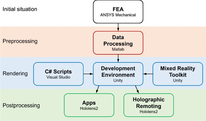
Workflow and software interaction in developing applications for engineering education
A further overview of augmented reality and virtual reality in the context of work, research and teaching was presented by Knoll and Stieglitz in the Springer journal “HMD Praxis der Wirtschaftsinformatik” in 2022 [ 3 ]. In this German publication, they discussed the opportunities and risks of open source projects, along with various industries and key areas of development.
In 2015, Huang et al. [ 4 ] developed a special application involving FEA with AR features, in which the stresses acting on the real objects were visually superimposed. In the case of a stepladder, force sensors were used to determine the acting loads. In the Springer Handbook of Augmented Reality, Huang et al. presented a detailed description of the development of an AR application integrated with FEA [ 5 ]. This comprehensive description illustrates a marker-based system that superimposes virtual FEA objects onto a real environment. The system, developed since 2015 [ 4 ], has been tested in various scenarios with different inputs and result options. The focus is on the calculation and interaction with a stepladder. This system includes features such as sensor integration, selection of objects using marker-based pointers, and the display of calculation results in the real environment. In contrast to the application developed in this work, the FE calculations or the FE mesh are presented on a 2D screen, not through an HMD device. The HMD device enables realistic 3D display with eye-tracking capabilities. Moreover, the FE mesh used in this application was of a coarse resolution.
The visualization of 3D objects in space with mobile devices was carried out by Passas-Burgos et al. in [ 6 ]. The study described the development of an open access tool for mobile devices that allowed the visualization of 3D objects through augmented reality. Visualizing 3D objects in space is both a challenge and a developable skill for engineering students, which the application presented in this paper aims to facilitate.
Another mobile application in engineering based on augmented reality technology was presented by Zhylenko et al. in [ 7 ]. The described form of education about the information transfer in a virtual environment is useful for avoiding the perception difficulties of graphic information by visualizing complex objects.
In 2022, Coronado et al. [ 8 ] provided an analysis of current augmented reality technologies and a review of the state of the art regarding augmented reality in teaching, focusing especially on engineering at the undergraduate level. The augmented reality simulation, presented as an app for mobile devices, allowed a three-dimensional representation of planar mechanisms as well as several possible interactions, plots, and calculations.
Jo et al. wrote and published a patent [ 9 ] proposing a system for training, education, and/or advertising of complex machinery in MR using the metaverse. The system included a simulation performance unit, configured to carry out three-dimensional simulations by providing a digital twin to perform simulations of a specific visual component for maintenance training, education, and/or advertising by means of smart glasses, as well as a training unit configured to provide artificial intelligence (AI).
As part of this project, two additional research works were conducted in cooperation with the IfE (Institute of Educational Science) at the University of Stuttgart and have been presented to the public. An AR development without HMD was described in [ 10 ] in 2021. Instructions for operating a complex turning/milling center were displayed here to the user on a smartphone or tablet. In the context of learning and teaching, a further publication [ 11 ] in 2022 presented explanations of the structure and individual components of the same turning/milling center, an Index R200, by means of the very realistic hologram with many individual components. The MR/AR app was tested in a 2-week pilot phase. In the pilot phase, it showed that it is difficult to exactly orientate the hologram to real bodies or rather that it requires a certain amount of practiceby the user. It is, however, easy to disassemble the virtual components. The results of the pilot phase have impacted the development of the use case introduced in this paper. The development process and outcomes described below open new avenues for interactive and engaging learning in engineering education.
3 Approach and methodology
The most valuable aspect of this work is a new method to collect simulation results, render them in Unity environment, and represent them on Hololens2. To display three-dimensional simulation results as holograms on smart glasses, various processing steps were necessary as the glasses can only reproduce 3D models of particular file formats. In this paper, the goal was to transform simulation results from the conventional FEA software into immersive moving 3D holograms, which can be experienced through smart glasses.
3.1 Application development process
Figure 1 illustrates the processing steps and software interactions involved in developing this application. The whole process is divided into four steps, namely the initial simulation, preprocessing, rendering, and postprocessing. Here, to differentiate the postprocessing of application development from the postprocessing of FEA, we use the term “simulation results” instead of “postprocessing of FEA.”
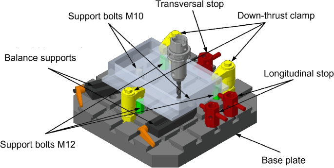
Workpiece-fixture system with various fixturing components
As the initial simulation, the simulation tasks were carried out using the commercial FEA software ANSYS Mechanical. MATLAB was then used to collect the data from ANSYS and prepare it for the next step in Unity, because this software offers the object-orientated numerical calculation of matrices. Unity, known for its robust capabilities in creating interactive real-time 3D (RT3D) content, was utilized for developing our application. According to the manufacturer’s information, 70% of the 1000 most popular games for mobile devices were developed with Unity [ 12 ]. To realize the different functions in various scenes, Unity offers the use of scripts in the C# language. The Microsoft Mixed Reality Toolkit, essential for connecting Microsoft Hololens2 to Unity, was employed in our development process.
After creating an AR application in Unity, we have two options for transferring the data to the Hololens2 HMD. This app can directly be created using Microsoft’s Visual Studio and then be installed into the Hololens2 headset. Alternatively, the data can also be transferred via the Holographic Remoting Player on the smart glasses. The holographic content was streamed from there to the HMD in real time. Both options were tested. Further details are explained in the following sections.
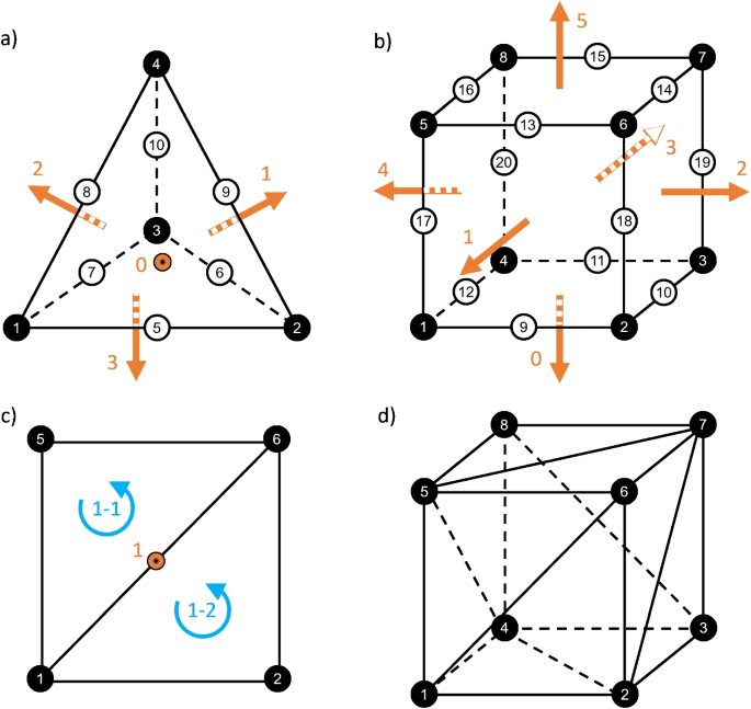
Rendering finite elements in Unity: a a tet10 element and b a hex20 element with the specified structure of nodal points; c dividing the visible quadrilateral surface (facing outside) into two triangles; d applying this divide to all surfaces of the hex20 element
3.2 Use case: clamping and machining task
For the application example, the clamping and machining situation was selected as shown in Fig. 2 . The clamping task was carried out in the framework of another project aimed at investigating the nonlinear, dynamic contact behavior between the workpiece and the clamping elements (Feng et al. [ 13 ] and [ 14 ]). The details of the clamping situation are not discussed in this paper, as it is focussed on the implementation of the holographic application for a complex use case and the tools developed for displaying FEA calculations on smart glasses (HMD).
A drilling operation in a corner of the workpiece was selected as the machining task. A deep pocket had already been milled into the aluminum workpiece, resulting in larger deformations and thus a more attractive representation of the calculation results. The drill had a diameter of D = 12 mm. The feed rate was f = 0.3 mm. The calculation according to the Victor-Kienzle formula [ 15 ] resulted in a feed force of 1136 N, which was used as a boundary condition in the FEA calculation.
3.3 Rendering the simulation results on Hololens2
This section details the method for rendering simulation results on the Hololens2 using Unity. In general, the models in Unity contain information about meshes, materials, and textures, defining their shape and appearance. The representation of 3D models in Unity can generally be divided into two approaches. The first option is to create models outside Unity and then import them. This can be carried out with the graphics file formats of .fbx, .dae, .dxf, and .obj. However, these formats were unsuitable for our intended application. The alternative is manually creating a mesh and assigning materials to define its appearance. This method provides a wide range of visual options offered by the Unity development environment. We utilized the latter approach the mesh class, which can be accessed via C# scripts.
In FEA, tetrahedral elements with ten nodes (tet10) and hexahedral elements with twenty nodes (hex20) were employed. These elements can be described by characteristic elements with specified structures of nodal points, as shown in Fig. 3 a and b. In Unity or on Hololens2, it is sufficient to represent only the envelopes of the models using the surface mesh instead of modeling the entire bodies. In this way, the computing time of HoloLens2 can be efficiently saved by ignoring irrelevant information inside the model. Therefore, only the information of nodes on surfaces is required. We developed a MATLAB program especially to search for all these nodes and to label the simulation results on them (Table 1 ).
The greatest challenge is that Unity can only render tetrahedral elements, while the FEA mesh contains both tetrahedral and hexahedral elements. To render the quadrilaterals visible on the outer surface of the hexahedra, we developed a special algorithm using MATLAB.
Our algorithm divides the quadrilateral into two triangles, as shown in Fig. 3 c and d. Because Unity distinguishes between visible surfaces facing outside and invisible surfaces facing inside from the perspective of the viewer. This means that the nodes in the index array must be arranged in an anti-clockwise direction to render a visible surface. Finally, the corresponding attributes (e.g., colors) are assigned to both triangle arrays.
Each node of the mesh assumes a unique color within the application. To configure the coloration of the visualized models, we first calculate the differential between each node’s current and original positions. Subsequently, the InverseLerp function is employed to compute the color value \( \lambda \) , which ranges from zero to one:
where \( \textbf{r}_0 \) is the original position of the node, \( \textbf{r}_{\text {max}} \) is the position of the node at maximum deformation and \( \textbf{r}_{\text {curr.}} \) represents the node’s current position:
\( \lambda \) is then utilized to select a specific hue from a predefined gradient scale, enabling the models to be displayed in a manner similar to the simulation results in ANSYS.
4 Development and presentation of the features of the augmented reality application
The following section describes the structure and menu navigation as well as the interaction options available to the user when operating the application with the HoloLens 2 HMD. The menu navigation in the application is characterized by calling up an extra scene for each menu. Figure 4 shows the conceptual design of the application, providing a brief overview of its operation across six scenes. The individual scenes are described below, detailing what the user sees and the interaction options available in each scene.
4.1 Scene 1: start the application
The application can be selected and started from the start menu of the MR headset using the classic two-hand gesture on the wrist.
4.2 Scene 2: set up of virtual model
In this scene, the user is instructed to spatially position the model for further viewing. To do this, the user has to grip the model by hand as shown in Fig. 5 and move it to a position that allows enough space around the model for viewing. Upon gripping the model, a feedback sound is emitted, and the color of the model changes to a light shade of grey. These functions are intended to provide the user with an intuitive operability of the model and an initial feeling for handling it.
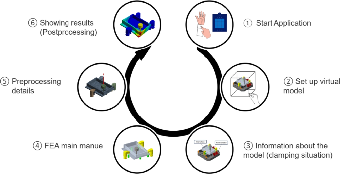
A brief overview of individual scenes in the augmented reality application

Spatial positioning of the AR model by gripping it with the hand
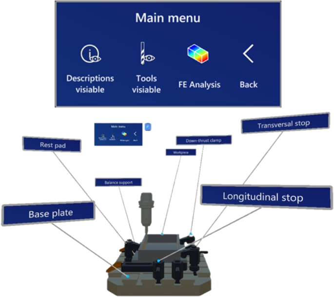
Upper: main menu for Scene 3. Lower: exemplary designations of the components in the AR model and illustration of the machining process

Left: the main menu of FE analysis for Scene 4. Right: the simplified AR model of the clamping fixture

Left: the menu of preprocessing for Scene 5. Right: visualization of meshing in the AR evironment
Furthermore, an arrow that is faded in as soon as the user looks away from the model makes operation easier. This arrow always points in the direction of the model. Once the user has finally positioned the model, he has to confirm this by pushing the Next button. The position is then maintained for the entire application, but can be changed at any time by returning to this menu. The user can also use this function later to place the model in the desired position in the real machine tool.
4.3 Scene 3: main menu and information about the model
In this scene, the user can gain an overview of the clamping device. He has the option here to display the designations of the individual components. These designations always orientate themselves to the viewing direction of the user, allowing the model to be seen from different positions (Fig. 6 ).
Fading in the drill shows which machining task is to be carried out. Then the drill carries out an animated stroke movement to indicate that a hole will be drilled at this point. The next scene is called up by tapping the FE Analysis button.
4.4 Scene 4: the main menu of FE analysis
The main menu of FE analysis (Fig. 7 ) presents a simplified model for the simulation. The user can fade in information describing and explaining these simplifications. They were made to save computing power and thus reduce display errors.
The other buttons in the menu are based on the structure of FE simulation software. The user can choose between preprocessing and various postprocessing options. The following options are available for the holographic visualization of the results:
Total deformation
Equivalent stress
Modal analysis
From these submenus, the user can always return to this FE main menu via a back button.

Left: the menu of postprocessing (the total deformation) for Scene 6a. Right: deformed AR model with coloring according to the degree of deformation
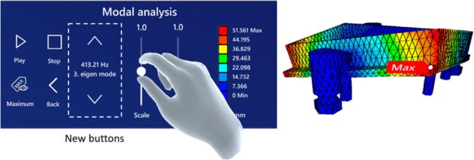
Left: the menu of postprocessing (the model analysis) for Scene 6c. Right: mapping of the eigenmode with color on the AR glasses
4.5 Scene 5: preprocessing
The MR headset is responsible solely for the postprocessing of the simulation model, while the preprocessing and the solver process are executed using ANSYS. In this scene, key components of the preprocessing are visualized to give the user essential background information about the simulation. As depicted in Fig. 8 , this visualization includes the mesh utilized in the simulation. Additionally, boundary conditions such as the clamping, bearing, and the force applied by the machining operation are also displayed.
4.6 Scene 6a: postprocessing - total deformation
This scene, along with the subsequent ones, encompasses the core elements of the task, namely, the postprocessing of the FE simulation. The results of the simulation are fully duplicated into the AR headset. In these final stages of the developed application, users can independently assess the quality of the clamping situation based on the simulation results they have reviewed.
As shown on the left side of Fig. 9 , the control panel is divided into the following areas: buttons, slide controls, and a scale. The Play and Stop buttons are located on the left side of the menu. Pressing “Play” causes the model to alternate between its undeformed and deformed states. The color of the bodies is also changing continuously. Pressing “Stop” halts this movement, and the model is then displayed in its deformed state again. When the “Maximum” button is pressed, a label indicating the point of maximum deformation appears. This label always aligns itself with the user’s viewing direction.
The exaggerated displacement and the movement speed can be adjusted using both slide controls, which must be operated between the thumb and index finger. Once the scene is activated, the color scale values are displayed. The model’s deformation is represented by an equidistant distribution in millimeters, with coloring based on the degree of deformation.
4.7 Scene 6b: postprocessing - equivalent stress
The equivalent stress in the clamping fixture can be inspected similarly to the total deformation (Scence 6a). The values of the equivalent stress are given in MPa. The scalar values for exaggeration, speed, or the color scale are adjusted accordingly. The model changes its coloration based on the level of equivalent stress and deforms based on the data of the total deformation as well.
4.8 Scene 6c: postprocessing - modal analysis
To inspect the modal analysis, the menu shown on the left in Fig. 10 is enhanced with new buttons for selecting eigenmodes. Here, the third natural frequency is selected, and the corresponding displacement is displayed on the right side of Fig. 10 . However, other eigenmodes can be shifted using the additional buttons. Similar to the total deformation, when the “Play” button is pressed, the model deforms according to the selected eigenmode.
5 Testing the augmented reality application in a real research environment
During extensive testing of the new AR application for assessing clamping concepts, it was found that the application on the Hololens2 crashed after a certain period of use, especially when viewing the scenes that assess the simulation results involving movements. The reason was identified as the Hololens2’s memory of 4 GB, which was filled rapidly by the AR application.
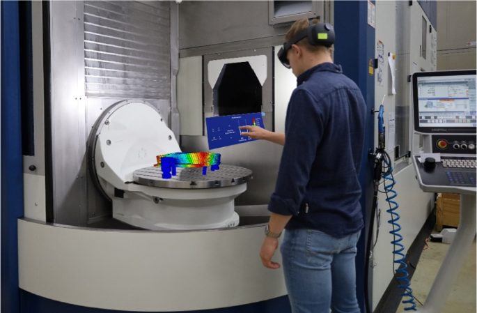
Testing the AR application in the real environment on a milling table
By incorporating an additional external PC, the application’s usability period was extended indefinitely. The PC or notebook was connected to the Hololens2 via Unity, using the Holographic Remoting Player app. The remote PC, with its 32 GB of main memory and internal hard disk, was used to temporarily swap data. With a robust Wi-Fi connection and a suitable PC (i7 with GeForce GTX 1650, 32 GB Ram), the frame rate (FPS) on the Hololens2 increased from 25 to 33. If the movements of the vibrations or deformations are operated exclusively on the PC, achieving 50 FPS is feasible.
To demonstrate how users could perceive calculated results in a real-world setting, an image shows the clamping situation in the Grob 550 machining center, which is available at the Institute for Machine Tools. This machine was also utilized for the cutting tests with the previously mentioned clamping situation [ 13 , 14 ]. Figure 11 illustrates that the user can view the results in the form of a hologram on the milling machine table, accurately reflecting the exaggerated deformation or natural modes of the clamping fixtures.
In the example presented, the user can select the desired calculated natural frequency and adjust the exaggeration or the color gradient. Unlike the PC representation, the result is a three-dimensional moving hologram with a changing color gradient, closely resembling real-life scenarios. Moreover, the observer can view the workpiece and clamping elements from various angles and positions. This visualization aids engineering students in more effectively understanding the cutting process and the workpiece clamping technology.
6 Summary and outlook
The aim of this research work was to develop an AR application that expands the capabilities of evaluating FE simulation results by means of AR technology. Using a clamping scenario with a specific machining task as an example, this application enables users, vocational students, or technicians, who have limited background in finite element analysis and machining, to immersively experience and independently assess the quality of the clamping.
MATLAB scripts served as an interface between FEA and the Unity development environment for processing the exported simulation data. This data interface could be applied to any simulation model composed of tetrahedral and/or hexahedral elements. Hence, the postprocessing with the HMD can be easily adapted for other models and be expanded for other engineering scenarios.
Testing and using the application on the Hololens2 created a remarkable immersive effect. Both experienced users familiar with Hololens2 applications and first-time users considered this research-derived use case as an intriguing FEA scenario, allowing them to immerse themselves in a novel world of learning and experience.
In the future, we plan to conduct a thorough comparison of our final outcomes with prior research and relevant studies. Moreover, we aim to underscore the benefits and effectiveness of our method by employing established criteria.

Data availability
Materials, datasets, and software used in the study are available from the corresponding author upon reasonable request.
Code Availability
The code used in this study is available from the corresponding author upon reasonable request.
Milgram P, Takemura H, Utsumi A, Kishino F (1995) Augmented reality: a class of displays on the reality-virtuality continuum, vol 2351, pp 282–292. https://doi.org/10.1117/12.197321
Al-Ansi AM, Jaboob M, Garad A, Al-Ansi A (2023) Analyzing augmented reality (AR) and virtual reality (VR) recent development in education. Soc Sci Humanit Open 8(1):100532. https://doi.org/10.1016/j.ssaho.2023.100532
Article Google Scholar
Knoll M, Stieglitz S (2022) Augmented reality und virtual reality-Einsatz im Kontext von Arbeit, Forschung und Lehre. HMD Praxis der Wirtschaftsinformatik 59(1):6–22. https://doi.org/10.1365/s40702-022-00840-5
Huang J, Ong S-K, Nee AY (2015) Real-time finite element structural analysis in augmented reality. Adv Eng Softw 87:43–56. https://doi.org/10.1016/j.advengsoft.2015.04.014
Huang J, Ong SK, Nee AYC (2023) An augmented reality platform for interactive finite element analysis, pp 533–574. https://doi.org/10.1007/978-3-030-67822-7_22
Parras-Burgos D, Melgarejo-Torralba M, Cañavate FJ, Fernández-Pacheco DG (2022) Graphic interpretation of surfaces with the support of augmented reality as a training complement in engineering studies, 318–326. https://doi.org/10.1007/978-3-030-92426-3_37
Zhylenko T, Ivanov V, Pavlenko I, Martynova N, Zuban Y, Samokhvalov D (2021) Mobile applications in engineering based on the technology of augmented reality, pp 366–376. https://doi.org/10.1007/978-3-030-79168-1_33
Urbina Coronado PD, Demeneghi JAA, Ahuett-Garza H, Orta Castañon P, Martínez MM (2022) Representation of machines and mechanisms in augmented reality for educative use. Int J Interact Des Manuf (IJIDeM) 16(2):643–656. https://doi.org/10.1007/978-3-030-79168-1_33
Jo GS, Siyaev A (2023) Training, education and/or advertising system for complex machinery in mixed reality using metaverse platform. US Patent App. 17/566,871
Völpel D (2023) Using augmented reality to convey teaching content. forschung leben – the magazin of the University of Stuttgart. https://www.uni-stuttgart.de/en/research/forschung-leben/1-2021/augmented-reality/ (Retrieved September 27, 2023)
Maier W, Rothmund J, Möhring H-C, Dang P-D, Hoffarth E, Zinn B, Wyrwal M (2022) Experiencing the structure and features of a machine tool with mixed reality. Procedia CIRP 106:244–249. https://doi.org/10.1016/j.procir.2022.02.186
Unity - our company. https://unity.com/de/our-company (Retrieved September 27, 2023)
Feng Q, Maier W, Braun S, Möhring H-C (2023) Detection and identification of nonlinear contact dynamics at workpiece clamping positions. Journal of Machine Engineering 23:114–122. https://doi.org/10.36897/jme/161718
Feng Q, Maier W, Braun S, Möhring H-C (2023) Dynamic modeling of the workpiece-fixture contact behavior for intelligent fixture design. Procedia CIRP 119:58–65. https://doi.org/10.1016/j.procir.2023.02.126
Kienzle O (1952) Die bestimmung von kräften und leistungen an spanenden werkzeugen und werkzeugmaschinen. VDI-Z 94(11):299–305
Google Scholar
Download references
Open Access funding enabled and organized by Projekt DEAL. This paper was written as part of the LEBUS2 project (Teacher Training at Vocational Schools 2 in the framework of the quality initiative for teacher training), funded by the Federal Ministry of Education and Research (BMBF), Germany with the grant number: 01JA1902.
Author information
Authors and affiliations.
Institute for Machine Tools, University of Stuttgart, Holzgartenstr. 17, 70174, Stuttgart, Germany
Walther Maier, Hans-Christian Möhring, Qi Feng & Richard Wunderle
Graduate School of Excellence advanced Manufacturing Engineering (GSaME), University of Stuttgart, Nobelstr. 12, 70569, Stuttgart, Germany
You can also search for this author in PubMed Google Scholar
Contributions
Walther Maier conceived of the presented idea and led the project. Walther Maier, Qi Feng, and Richard Wunderle contributed to the implementation of the research. Prof. Hans-Christian Möhring provided invaluable advice, offered critical feedback, and guided the direction of the research project. Walther Maier and Qi Feng contributed to the final manuscript.
Corresponding authors
Correspondence to Walther Maier or Qi Feng .
Ethics declarations
Conflict of interest.
The authors declare no competing interests.
Additional information
Publisher's note.
Springer Nature remains neutral with regard to jurisdictional claims in published maps and institutional affiliations.
Rights and permissions
Open Access This article is licensed under a Creative Commons Attribution 4.0 International License, which permits use, sharing, adaptation, distribution and reproduction in any medium or format, as long as you give appropriate credit to the original author(s) and the source, provide a link to the Creative Commons licence, and indicate if changes were made. The images or other third party material in this article are included in the article’s Creative Commons licence, unless indicated otherwise in a credit line to the material. If material is not included in the article’s Creative Commons licence and your intended use is not permitted by statutory regulation or exceeds the permitted use, you will need to obtain permission directly from the copyright holder. To view a copy of this licence, visit http://creativecommons.org/licenses/by/4.0/ .
Reprints and permissions
About this article
Maier, W., Möhring, HC., Feng, Q. et al. Augmented reality to visualize a finite element analysis for assessing clamping concepts. Int J Adv Manuf Technol (2024). https://doi.org/10.1007/s00170-024-13960-7
Download citation
Received : 08 February 2024
Accepted : 30 May 2024
Published : 07 June 2024
DOI : https://doi.org/10.1007/s00170-024-13960-7
Share this article
Anyone you share the following link with will be able to read this content:
Sorry, a shareable link is not currently available for this article.
Provided by the Springer Nature SharedIt content-sharing initiative
- Augmented reality
- Clamping fixture
- Finite element analysis
- Find a journal
- Publish with us
- Track your research
Information
- Author Services
Initiatives
You are accessing a machine-readable page. In order to be human-readable, please install an RSS reader.
All articles published by MDPI are made immediately available worldwide under an open access license. No special permission is required to reuse all or part of the article published by MDPI, including figures and tables. For articles published under an open access Creative Common CC BY license, any part of the article may be reused without permission provided that the original article is clearly cited. For more information, please refer to https://www.mdpi.com/openaccess .
Feature papers represent the most advanced research with significant potential for high impact in the field. A Feature Paper should be a substantial original Article that involves several techniques or approaches, provides an outlook for future research directions and describes possible research applications.
Feature papers are submitted upon individual invitation or recommendation by the scientific editors and must receive positive feedback from the reviewers.
Editor’s Choice articles are based on recommendations by the scientific editors of MDPI journals from around the world. Editors select a small number of articles recently published in the journal that they believe will be particularly interesting to readers, or important in the respective research area. The aim is to provide a snapshot of some of the most exciting work published in the various research areas of the journal.
Original Submission Date Received: .
- Active Journals
- Find a Journal
- Proceedings Series
- For Authors
- For Reviewers
- For Editors
- For Librarians
- For Publishers
- For Societies
- For Conference Organizers
- Open Access Policy
- Institutional Open Access Program
- Special Issues Guidelines
- Editorial Process
- Research and Publication Ethics
- Article Processing Charges
- Testimonials
- Preprints.org
- SciProfiles
- Encyclopedia

Article Menu

- Subscribe SciFeed
- Recommended Articles
- Author Biographies
- Google Scholar
- on Google Scholar
- Table of Contents
Find support for a specific problem in the support section of our website.
Please let us know what you think of our products and services.
Visit our dedicated information section to learn more about MDPI.
JSmol Viewer
A study on the effects of cementless total knee arthroplasty implants’ surface morphology via finite element analysis.

1. Introduction
2.1. implant model, 2.2. bone model, 2.3. interactions, 2.4. applied loads and bcs, 2.5. mesh generation, 2.6. configurations, 2.7. post-processing, 3.1. global results: optimal coefficient of friction, 3.2. global results: optimal coating location, 3.3. local results: optimal coefficient of friction, 3.4. local results: optimal coating location, 4. discussion, 4.1. stress-shielding results, 4.2. similarity between configurations, 4.3. global and local results, 4.3.1. optimal coefficient of friction, 4.3.2. optimal coating location, 5. conclusions, author contributions, institutional review board statement, informed consent statement, data availability statement, conflicts of interest.
- Pabinger, C.; Lothaller, H.; Geissler, A. Utilization rates of knee-arthroplasty in OECD countries. Osteoarthr. Cartil. 2015 , 23 , 1664–1673. [ Google Scholar ] [ CrossRef ] [ PubMed ]
- Memtsoudis, S.G.; della Valle, A.G.; Besculides, M.C.; Gaber, L.; Demographics, R.L.T.I.; Profiles, C. In-Hospital Complications and Mortality Associated with Primary Knee Arthroplasty. J. Arthroplast. 2009 , 24 , 518–527. [ Google Scholar ] [ CrossRef ]
- Schrurs, W.B.; Hannink, G. Total joint arthroplasty in younger patients: Heading for trouble? Lancet 2017 , 389 , 1410–1423. [ Google Scholar ] [ CrossRef ] [ PubMed ]
- Forlenza, E.M.; Serino, J., 3rd; Terhune, E.B.; Weintraub, M.T.; Nam, D.; Della Valle, C.J. Cementless Total Knee Arthroplasty is Associated With Early Aseptic Loosening in a Large National Database. J. Arthroplast. 2023 , 38 , S215–S220. [ Google Scholar ] [ CrossRef ] [ PubMed ]
- Lum, Z.C.; Shieh, A.K.; Dorr, L.D. Why total knees fail-A modern perspective review. World J. Orthop. 2018 , 9 , 60–64. [ Google Scholar ] [ CrossRef ] [ PubMed ]
- American Academy of Orthopaedic Surgeons (AAOS); American Joint Replacement Registry (AJRR). 2019 Annual Report ; American Academy of Orthopaedic Surgeons: Rosement, IL, USA, 2019. [ Google Scholar ]
- Kamath, A.F.; Siddiqi, A.; Malkani, A.L.; Krebs, V.E. Cementless Fixation in Primary Total Knee Arthroplasty: Historical Perspective to Contemporary Application. J. Am. Acad. Orthop. Surg. 2021 , 29 , e363–e379. [ Google Scholar ] [ CrossRef ] [ PubMed ]
- Matassi, F.; Carulli, C.; Civinini, R.; Innocenti, M. Cemented versus cementless fixation in total knee arthroplasty. Joints 2014 , 1 , 121–125. [ Google Scholar ] [ CrossRef ] [ PubMed ]
- Fenton, P.; Al-Nammari, S.; Blundell, C.; Davies, M. The patterns of injury and management of cuboid fractures A RETROSPECTIVE CASE SERIES. Bone Jt. J. 2016 , 98B , 1003–1008. [ Google Scholar ] [ CrossRef ]
- van der List, J.P.; Sheng, D.L.; Kleeblad, L.J.; Chawla, H.; Pearle, A.D. Outcomes of cementless unicompartmental and total knee arthroplasty: A systematic review. Knee 2017 , 24 , 497–507. [ Google Scholar ] [ CrossRef ]
- Bahraminasab, M.; Sahari, B.B.; Edwards, K.L.; Farahmand, F.; Arumugam, M. Aseptic loosening of femoral components—Materials engineering and design considerations. Mater Des. 2013 , 44 , 155–163. [ Google Scholar ] [ CrossRef ]
- Damm, N.B.; Morlock, M.M.; Bishop, N.E. Friction coefficient and effective interference at the implant-bone interface. J. Biomech. 2015 , 48 , 3517–3521. [ Google Scholar ] [ CrossRef ] [ PubMed ]
- Sánchez, E.; Schilling, C.; Grupp, T.M.; Giurea, A.; Wyers, C.; van den Bergh, J.; Verdonschot, N.; Janssen, D. The effect of different interference fits on the primary fixation of a cementless femoral component during experimental testing. J. Mech. Behav. Biomed. Mater. 2021 , 113 , 104189. [ Google Scholar ] [ CrossRef ] [ PubMed ]
- Berahmani, S.; Janssen, D.; Wolfson, D.; Rivard, K.; de Waal Malefijt, M.; Verdonschot, N. The effect of surface morphology on the primary fixation strength of uncemented femoral knee prosthesis: A cadaveric study. J. Arthroplast. 2015 , 30 , 300–307. [ Google Scholar ] [ CrossRef ]
- de Vries, E.; Sánchez, E.; Janssen, D.; Matthews, D.; van der Heide, E. Predicting friction at the bone–Implant interface in cementless total knee arthroplasty. J. Mech. Behav. Biomed. Mater. 2022 , 128 , 105103. [ Google Scholar ] [ CrossRef ] [ PubMed ]
- Berahmani, S.; Janssen, D.; Verdonschot, N. Experimental and computational analysis of micromotions of an uncemented femoral knee implant using elastic and plastic bone material models. J. Biomech. 2017 , 61 , 137–143. [ Google Scholar ] [ CrossRef ] [ PubMed ]
- Morrison, I.B. The mechanics of the knee joint in relation to normal walking. J. Biomech. 1970 , 3 , 51–61. [ Google Scholar ] [ CrossRef ] [ PubMed ]
- Walpole, S.C.; Prieto-Merino, D.; Edwards, P.; Cleland, J.; Stevens, G.; Roberts, I. The weight of nations: An estimation of adult human biomass. BMC Public Health 2012 , 12 , 439. [ Google Scholar ] [ CrossRef ] [ PubMed ]
- Zhao, D.; Banks, S.A.; D’Lima, D.D.; Colwell, C.W.; Fregly, B.J. In vivo medial and lateral tibial loads during dynamic and high flexion activities. J. Orthop. Res. 2007 , 25 , 593–602. [ Google Scholar ] [ CrossRef ] [ PubMed ]
- Fukubayashi, T.; Kurosawa, H. The contact area and pressure distribution pattern of the knee: A study of normal and osteoarthrotic knee joints. Acta Orthop. 1980 , 51 , 871–879. [ Google Scholar ] [ CrossRef ]
- Completo, A.; Talaia, P.; Fonseca, F.; Simões, J.A. Relationship of design features of stemmed tibial knee prosthesis with stress shielding and end-of-stem pain. Mater Des. 2009 , 30 , 1391–1397. [ Google Scholar ] [ CrossRef ]
- Au, A.G.; Liggins, A.B.; Raso, V.J.; Amirfazli, A. A parametric analysis of fixation post shape in tibial knee prostheses. Med. Eng. Phys. 2005 , 27 , 123–134. [ Google Scholar ] [ CrossRef ] [ PubMed ]
| Geometric Feature | Dimension |
|---|---|
| Stem | Diameter: ~14.7 mm Length: ~40 mm |
| Pegs | Diameter: 6 mm Length: 10 mm |
| Baseplate | Thickness: 4 mm |
| Material | Young’s Modulus (GPa) | Poisson’s Ratio |
|---|---|---|
| Titanium | 110 | 0.3 |
| Cortical bone | 14.2 | 0.3 |
| Trabecular bone | 1.75 | 0.3 |
| Description | Coefficient of Friction |
|---|---|
| Uncoated | 0.15 |
| Grit-blasted | 0.5 |
| Porocoat | 0.95 |
| DePuy Synthes experimental | 1.4 |
| High control | 2 |
| The statements, opinions and data contained in all publications are solely those of the individual author(s) and contributor(s) and not of MDPI and/or the editor(s). MDPI and/or the editor(s) disclaim responsibility for any injury to people or property resulting from any ideas, methods, instructions or products referred to in the content. |
Share and Cite
Hunt, P.J.; Noori, M.; Hazelwood, S.J.; Noori, N.B.; Altabey, W.A. A Study on the Effects of Cementless Total Knee Arthroplasty Implants’ Surface Morphology via Finite Element Analysis. BioMedInformatics 2024 , 4 , 1425-1440. https://doi.org/10.3390/biomedinformatics4020078
Hunt PJ, Noori M, Hazelwood SJ, Noori NB, Altabey WA. A Study on the Effects of Cementless Total Knee Arthroplasty Implants’ Surface Morphology via Finite Element Analysis. BioMedInformatics . 2024; 4(2):1425-1440. https://doi.org/10.3390/biomedinformatics4020078
Hunt, Peter J., Mohammad Noori, Scott J. Hazelwood, Naudereh B. Noori, and Wael A. Altabey. 2024. "A Study on the Effects of Cementless Total Knee Arthroplasty Implants’ Surface Morphology via Finite Element Analysis" BioMedInformatics 4, no. 2: 1425-1440. https://doi.org/10.3390/biomedinformatics4020078
Article Metrics
Article access statistics, further information, mdpi initiatives, follow mdpi.

Subscribe to receive issue release notifications and newsletters from MDPI journals
- DOI: 10.1080/15397734.2024.2353896
- Corpus ID: 270328407
Damage analysis of functionally graded materials: A finite element investigation utilizing the Gurson–Tvergaard–Needleman (GTN) model for notched plates
- Amir Slamene , Mohamed Mokhtari , +3 authors Abderraouf Ousidhoum
- Published in Mechanics based design of… 5 June 2024
- Engineering, Materials Science
65 References
Simplified homogenization technique for nonlinear finite element analysis of in-plane loaded masonry walls, accurate free and forced vibration behavior prediction of functionally graded sandwich beams with variable cross-section: a finite element assessment, damage analysis of functionally graded materials under strong cyclic loading, free vibration and bending analysis of porous bi-directional fgm sandwich shell using a tsdt p-version finite element method, using fgm concept in fiber-matrix coupling laws to predict the damage in carbon-epoxy graded composite application in notched plate under thermo-mechanical loading, investigation on the mechanical genes of “rigidity-flexibility balance” composite materials similar to feather shaft by sr-ct in-situ experiments, an xfem model of cracked functionally graded materials under different dynamic loadings, using xfem technique to predict the crack growth in the notched plate under high loading cyclic conditions, sensitivity analysis of gtn damage parameters: application to notched plate ductile fracture simulation, nonlinear czm-based predictive analysis of damage in single-lap composite joints: an exploration of the fgm concept in fiber–matrix coupling, related papers.
Showing 1 through 3 of 0 Related Papers
Subscribe to the PwC Newsletter
Join the community, edit social preview.
Add a new code entry for this paper
Remove a code repository from this paper, mark the official implementation from paper authors, add a new evaluation result row.
| TASK | DATASET | MODEL | METRIC NAME | METRIC VALUE | GLOBAL RANK | REMOVE |
|---|
Remove a task
Add a method, remove a method, edit datasets, positivity preserving finite element method for the gross-pitaevskii ground state: discrete uniqueness and global convergence.
27 May 2024 · Moritz Hauck , Yizhou Liang , Daniel Peterseim · Edit social preview
We propose a positivity preserving finite element discretization for the nonlinear Gross-Pitaevskii eigenvalue problem. The method employs mass lumping techniques, which allow to transfer the uniqueness up to sign and positivity properties of the continuous ground state to the discrete setting. We further prove that every non-negative discrete excited state up to sign coincides with the discrete ground state. This allows one to identify the limit of fully discretized gradient flows, which are typically used to compute the discrete ground state, and thereby establish their global convergence. Furthermore, we perform a rigorous a priori error analysis of the proposed non-standard finite element discretization, showing optimal orders of convergence for all unknowns. Numerical experiments illustrate the theoretical results of this paper.
Code Edit Add Remove Mark official

IMAGES
VIDEO
COMMENTS
Abstract and Figures. The finite element method (FEM) is a numerical analysis technique for obtaining approximate solutions to a wide variety of engineering problems. A finite element model of a ...
An International Journal for Innovations in Computational Methodology and Application. The aim of this journal is to provide ideas and information involving the use of the finite element method and its variants, both in scientific inquiry and in professional practice. The scope is intentionally broad, encompassing use of the finite element ...
Finite Element Analysis has become an indispensible tool for many engineers and other scientists. The sophistication of the method, its accuracy, simplicity, and computability all make it a widely used tool in the engineering modeling and design process. This paper will discuss nite element analysis from mathematical theory to applications.
9 mixed methods Dual mixed method Instead of integrating by parts in the second equation, we can formally integrate by parts in the ˙rst equation of (9.14). To make this well-de˙ned, we set div„Ω":=. 2 2„Ω" : div 2 2„Ω". Ł endowed with the graph norm k k2 div„Ω". := k k2 2„Ω" ‚kdiv k.
In the last eighty years, finite element method (FEM) has grown to a prominent partial differential equation solver in the computational mechanics field [].Finite element analysis (FEA) is being widely used due to its ability to address a variety of problem domains including structural mechanics, fluid flow analysis, heat conduction, additive manufacturing, electrical and electronics field ...
Analysis: The dataset prepared by the preprocessor is used as an input to the finite element code, which constructs and solves a system of linear or nonlinear algebraic equations. The formation of the stiffness matrix is dependent on the type of problem under consideration, and this module will outline the approach for truss and linear elastic ...
Each finite element is solved independently and later, overall solution for the continuum is obtained by combining these individual finite element results. Various finite elements have been proposed to facilitate analysis of new phenomena and to improve existing methods. This paper is written to provide brief introduction to FEA…. Expand.
I. (1941-1965) The birth of the finite element method The origin of the finite element method as a numerical modeling paradigm may be traced back to in early 1940's. In 1941, A. Hrennikoff, a Russian-Canadian structural engineer at the University of British Columbia, published a paper in ASME Journal of Applied Mechanics on his membrane
Finite Element Analysis can abe this exact solution for these short comings as they were in other engineering disciplines [1, 2, performed again to achieve an optimal design that is 3]. nd Analysis are discretization methods that model the structural and thermal systems in segments also known as finite elements [4]. Each individual
The first design variable is the applied displacement, at point 1, which acts either in the positive x-direction or in the negative y-direction. The second design variable is a torque, acting around the negative z-axis at point 2, which is either active or not. Point 2 is constrained in all displacement.
This paper presents the finite element (FE) analysis and modelling of square concrete-filled steel tube (CFST) members subjected to a flexural load. A parametric study is conducted using the verified FE model to study the effect of the depth-to-thickness (D/t) ratio (18.75, 25, and 30), the compressive strength of infilled concrete (60, 80, and ...
6.3 Finite element mesh depicting global node and element numbering, as well as global degree of freedom assignments (both degrees of freedom are fixed at node 1 and the second degree of freedom is fixed at node 7) . . . . . . . . . . . . . 145
Summary. This chapter introduces the finite element method as a method by which the exact solution of a mathematical problem, cast in a generalized form, can be approximated. It also introduces the relevant mathematical concepts, terminology and notation in the simplest possible setting. The chapter considers the formulation of a second order ...
rigorous, detailed books in the area of finite element analysis. Through teaching finite element classes for a number of years at UC Berkeley, my experience has been that the fundamental weaknesses in prerequisite mathematics, such as vector calculus, linear algebra, and basic mechanics, exemplified by linearized elasticity, cause conceptual ...
This Special Issue on Finite Element Analysis and Simulation of Materials focuses on the publication of original research related to: - the structure, mechanical, electronic, chemical, magnetic, optical properties and various applications of classes of materials such as metals and alloys, polymers, composites, ceramics, glasses and ...
Finite element analysis plays an extremely important role in biomechanical research, especially in analyzing the relationship between different surgical models and the degeneration caused by different mechanics. As the elderly population continues to grow, the number of patients with low back pain is gradually increasing. Among them, Lumbar Degenerative Diseases (LDD) is one of the major ...
The finite element method (FEM), or finite element analysis (FEA), is a computational technique used to obtain approximate solutions of boundary value problemsin engineering. Boundary value problems are also called field problems. The field is the domain of interest and most often represents a physical structure.
EA.pdf [5] Lazarus, T., and J. Argyris, 2013, "A ... research. He has published approximately 300 works (including journal papers, ... Finite Element Analysis . 1950s . Finite Element Analysis (FEA) is a computational method used to simulate, or predict, how a part, assembly, or process will behave under given conditions. Before FEA simulation,
This paper presents the development of an innovative augmented reality application for evaluating clamping concepts through visualizing the finite element analysis. The focus is on transforming the traditional simulation results into immersive, holographic displays, enabling users to experience and assess finite element analysis in three dimensions. The application development process involves ...
Feature papers represent the most advanced research with significant potential for high impact in the field. ... Download PDF Download PDF with Cover Download XML Download Epub. Browse Figures ... "A Study on the Effects of Cementless Total Knee Arthroplasty Implants' Surface Morphology via Finite Element Analysis" BioMedInformatics 4, no. 2: ...
@article{Slamene2024DamageAO, title={Damage analysis of functionally graded materials: A finite element investigation utilizing the Gurson-Tvergaard-Needleman (GTN) model for notched plates}, author={Amir Slamene and Mohamed Mokhtari and Billel Hamza and Sadek Gouasmi and Fatna Telli and Abderraouf Ousidhoum}, journal={Mechanics Based ...
Stay informed on the latest trending ML papers with code, research developments, libraries, methods, and datasets. ... Positivity preserving finite element method for the Gross-Pitaevskii ground state: discrete uniqueness and global convergence ... Numerical Analysis Numerical Analysis 35Q55, 65N12, 65N15, 65N25, 65N30 Contact ...