An Introduction to VHDL Data Types
In this post, we talk about the most commonly used data types in VHDL . We will also look at how we perform conversions between these types.
VHDL is considered to be a strongly typed language. This means every signal or port which we declare must use either one of the predefined VHDL types or a custom type which we have created.
The type which we use defines the characteristics of our data. We can use types which interpret data purely as logical values, for example. We can also use types which interpret our data as if it were a numeric value.
Whenever we assign data to a signal, the data which we assign must adhere to the rules of the types. The code will not compile correctly if we attempt to mix incompatible data types. As a result, it is often necessary to explicitly perform type conversions in VHDL.

Basic VHDL Types
With a few exceptions, every signal or port in a VHDL design fundamentally consists of one or more logical bits. We use the different types in VHDL to tell our tools how this collection of bits should be interpreted.
This means that the simplest type we can use in VHDL consists of a single logical bit. There are actually two different types we can use for this purpose.
Let's take a closer look at both of these types.
- bit Type in VHDL
The bit type is the simplest of all types in VHDL. We use this type to model a single logical value within our FPGA. The bit type can only ever have a value or either 1b or 0b.
The code snippet below shows the method we use to declare a bit type signal in VHDL.
When we assign single bit data types, we use apostrophes (') to represent the data. For example, if we want to set a single bit to 1b we would assign it to '1' in our code.
In the post on entities and architectures in VHDL , we saw how we use signals to model connections in our design. When we assign data to signals we use the <= symbol. We also use this symbol when assigning data to a port.
In VHDL, we can also use variables to model wires in our design. When we assign data to a variable we use the := symbol. We discuss variables in more depth in the post on VHDL process blocks .
The code snippet below shows how we can assign values to a signal or port which uses the bit type.
std_logic Type in VHDL
The other type which we can use to model a single bit in our FPGA is the std_logic type. Although this is similar to the bit type, we have a greater range of values which we can assign to our signal when we use this type.
The code snippet below shows how we declare a std_logic type signal in VHDL.
In a digital circuit, we are mainly concerned with binary data . However, we can also use drivers which set signals to values other than 0b or 1b. It is possible to drive the output of an FPGA pin to high impedance , for example.
The std_logic type attempts to capture this broader range of possibilities. In addition to this, it also models conditions where the logic value is unpredictable. This typically occurs due to errors in our design.
The table below shows the full list of values that the std_logic type can take in VHDL.
As with the bit type, we assign data to a std_logic type signal using apostrophes (') to represent the data. The code snippet below shows how we can assign values to a signal or port which uses the std_logic type.
- Uninitialised or Unknown Values
The std_logic type not only lets us model high impedance signals but also models unknown values. We can get unknown or uninitialised values in our design under two circumstances.
The first circumstance is the simplest to understand. If we have signals in our design which aren't assigned a value at the start of simulation, they will show as uninitialized until they are assigned data.
In the screen shot below we can see how an uninitialized signal looks in a simulation environment. This screen shot is taken from the Vivado design tool which shows the uninitialized signals in the design as orange in the wave viewer.
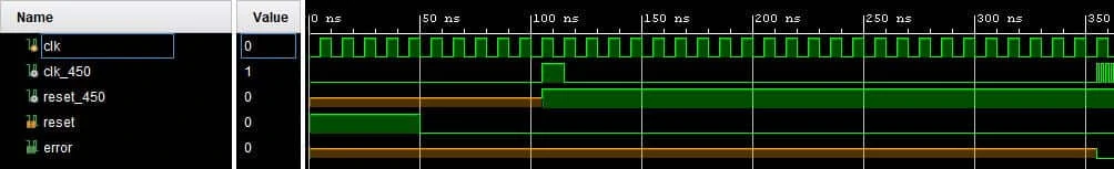
In this instance, the design uses a PLL to generate the internal clock signals. We can see here that the error signal is uninitialized until the PLL starts outputting a clock.
The second case when we can get unknown values occurs when we drive a signal from more than one source. As an example, consider the simple circuit diagram below which features 2 D type flip flops driving the same wire.
We should never intentionally design a digitial circuit which connects the output of 2 flip flops like this. The reason for this is that the behaviour of the circuit is not deterministic .
To demonstrate this, what would we expect the value of the signal to be if one fo the flip flops drove the output to 1b and the other drove it to 0b?
Actually, the answer is that we simply don't known. If we can't answer this question then it is quite clear that we have non-deterministic behaviour in our circuit.
When we write VHDL code, it is possible to create a non-deterministic circuit such as this one. This typically occurs if we assign data to a signal in more than one concurrent statement or process . This would lead to a signal which has an unknown value as our simulator can't determine what binary value it will actually take.
- Resolving std_logic Signals
When we design a digital circuit, there are occasions when we need to use circuits which have multiple drivers. For example, we may declare a port as an inout type so that we can use a bidirectional bus connected to an external flash device.
In VHDL, the std_logic type uses a concept known as resolution to allow us to use signals with multiple drivers.
To understand how resolution works in VHDL, we need to consider the drive strength of a signal. In a physical circuit, drive strength refers to the maximum amount of current it can deliver. A weak pull-up resistor can obviously deliver much less current than a MOSFET could.
The resolution function models this concept of drive strength to determine what value a signal should take when it is driven by multiple sources. To do this, a different effective drive strength is assigned to each of the possible states that a std_logic type can take.
When we drive a signal with two different values, the state with the highest drive strength takes precedent.
If we drive the signal with a mixture of '0' and '1' then the signal is assigned to the unknown ('U') state. This is because the '0' and '1' states have the same effective drive strength. When we use a mixture of the 'L' and 'H' states, the signal resolves to 'W' rather than 'U'.
The table below shows the modelled drive strength of the different std_logic states.

The code snippet below gives some basic examples which demonstrate the functionality of the resolution function.
- std_logic vs bit Type
Although we use the bit type and std_logic type to model the exact same thing in our design, the std_logic type is much more commonly used.
The main reason for this is that it provides a more realistic model of signals in a digital system. This is largely because it allows us to model various high impedance states.
Another advantage of the std_logic type is that the uninitialised state makes it easier to find signals which are not correctly driven. This is especially useful for finding bugs in circuits which feature a reset value.
Despite this, one advantage that the bit type has it that it will cause a compilation error when we design a circuit which features multiple drivers. In contrast to this, the std_logic type will compile code with multiple drivers.
However, it is normally easy to find bugs which arise due to the use of multiple drivers during simulation. This explains why the extra flexibility of the std_logic type makes it a more popular choice than the bit type despite this draw back.
There is also a std_ulogic type in VHDL which causes compilation errors when using multiple drivers. However, this type has no resolution function and is less commonly used that the std_logic type as a result.
VHDL Vector Types
The two types which we have looked at so far allow us to model single bits in our VHDL designs. However, we often use data buses which consist of multiple bits when we design digital circuits.
In VHDL, we can use vector types to model multiple bit buses. These vectors all consist of a number of bits which are modeled in a similar way to the std_logic or bit types.
Let's take a closer look at the most commonly used vector types in VHDL.
std_logic_vector and bit_vector Types
The most basic type of vector we can use in VHDL are made up of a number of bit or std_logic types. The code snippet below shows how we declare a vector type signal in VHDL.
The <range> field is used to determine the number of bits in the vector and the location of the most significant and least significant bits . We use the downto and to keywords to describe the range value in VHDL.
When we use the downto keyword, the msb is the left most bit in the signal. When we use the to keyword, the msb is the right most bit of the signal. The code snippet below shows how we would declare an 8 bit signal using both keywords.
- Assigning Data Values
When we assign data to vector types in VHDL we use quotation marks (") instead of apostrophes. We can also specify data using hexadecimal notation by appending an x to the start of the data. However, this only works if the number of bits in the vector is a factor of four.
The code snippet below gives some examples of how we assign data to vector types in VHDL.
When we are working with the VHDL-2008 standard we can also assign vector data using an octal number. This works in the same way as hex formatted data except we must replace the x with an o. The code snippet below gives an example of this.
We can also assign data to slices or single bits of the vector. To do this we must specify the range of bits we are assigning. The code snippet below shows the general syntax for this.
The <range> field in the above code snippet uses either the downto or to keyword to specify the slice we are assigning. It works in the exact same as the range field we talked about when declaring a vector type signal .
If we want to assign a single bit of the vector then we replace the range value with the index of the bit. However, in this case we must remember that we are assigning a single bit of data. This means that the data value must be enclosed by apostrophes rather than quotation marks.
The VHDL code snippet below shows some examples of assigning data to slices of a std_logic_vector type.
When we use bit slicing in this way, we will get compilation errors if we use an invalid range. For example, if we attempt to assign four bit data to a 3 bit slice this will cause an error.
Finally, there is one more useful function which we can use in VHDL to assign all of the bits of a vector to 1 or 0. We use the others keyword for this, as shown in the code snippet below.
- Signed and Unsigned VHDL Types
There are two more vector types which we often use in VHDL - signed and unsigned. In order to use these types, we need to include the numeric_std package from the standard ieee library.
When we use the signed type, the data is interpreted as a 2's complement number . This is in contrast to the unsigned type which is a normal binary number. This means that we can assign negative values to the signed type but not the unsigned type.
The VHDL code snippet below shows the general syntax for declaring a signal of both signed and unsigned type.
The signed and unsigned types are similar to the std_logic_vector type. However, we can also perform maths operations on them. In addition to this, we can also assign numerical data to them.
The code snippet below shows the two ways we can assign a value of four. This shows how it is possible to assign data either as a binary value or a base 10 integer type value.
The ieee.numeric_std VHDL library defines a number of mathematical operators which we can use with the signed and unsigned types. The table below shows the arithmetic operators we can use with these types.
The code snippet below shows how we use each of these arithmetic operators in practise.
These arithmetic operators require some consideration when we use them with synthesizable code though.
The plus, minus and multiplication operators can all be synthesized by most modern tools. However, this can often result in sub-optimal logical performance. As a result, it can be necessary to design logic circuits which specifically perform these functions.
We should never use the modulus or divide operators for synthesizable code as most tools will be unable to handle them.
- Integer Type
The integer data type is used to express a value which is a whole number in VHDL. This is similar to the integer type in other programming languages such as C.
The code snippet below shows the general syntax for declaring an integer type signal in VHDL. The <range> field is optional and we use this to limit the values the range of values integer can take in our VHDL design.
The integer type is similar to both the signed and unsigned types . We can use the integer type to express numbers and perform basic arithmetic operations.
The table below shows the mathematical operators we can use with the integer type.
We don't directly deal with bits when we are working with the integer type in VHDL. This is one of the key defining features which separates it from the signed and unsigned types.
As a result of this, we can't assign binary, hex or decimal type data to an integer. Instead, we always use a numeric value to assign data.
As with most programming lanaguges, the integer type in VHDL is 32-bits wide by default.
However, we can limit the range of the integer to save resources in our FPGA when writing VHDL code. For example, we may require a signal which counts from 0 to 150. Therefore, we can implement this as an 8 bit integer within our FPGA.
In order to limit the range of the integer, we specify the valid values the integer can take. We use the downto and to VHDL keywords which we have seen before to specify this range.
The code snippet below shows how we would declare an integer signal in VHDL which has a valid range from 0 to 150.
We can also use 2 integer subtypes in VHDL - natural and positive. The positive subtype can take the any positive integer value. The natural type is the same as the positive type except that it can also be assigned to 0.
VHDL Type Conversions
When we write VHDL code, we often have to convert between data types. There are two general methods which are available to us for this.
The first method is to simply cast the signal to the correct type. We can use this method to convert between the signed, unsigned and std_logic_vector VHDL data types.
The code snippet below shows the general syntax which we use to cast signals or data.
The second way we convert VHDL data types is through the use of a function. We normally use this method to convert between the signed or unsigned types and the integer type.
In order to use a suitable conversion function, we need to include either the numeric_std or std_logic_arith packages. Both of these packages are available in the IEEE library.
Although many engineers still use it, the std_logic_arith package is not officially supported by the IEEE standards and we should avoid using it . Therefore, we will only consider the functions which are included in the numeric_std package in this post.
The image below summarises the methods we use to convert between different data types in VHDL.
Let's look in more detail at the way we convert between the different data types in VHDL.
- Convert unsigned to std_logic_vector
To convert an unsigned type to a std_logic_vector we can simply cast the signal. However, whenever we do a cast we need to make sure that the signals have the same number of bits. If we don't do this then we will get an error.
The VHDL code below shows an example of casting the unsigned type to a std_logic_vector type.
- Convert unsigned to signed
As with the unsigned to std_logic_vector conversion, we can simply cast an unsigned type to a signed type. Again, we need to make sure that the signals have the same number of bits.
The code snippet below shows an example of casting the unsigned type to a signed type.
- Convert unsigned to integer
When we want to convert the unsigned type to an integer we have to use the to_integer function. This is a part of the numeric_std package in the ieee library so we must include this library and package in our code.
The code snippet below shows how we would include this library and package in our design.
After we have included the relevant package we can simply call the function to perform the required conversion. The VHDL code below shows an example where we use the to_integer function to convert an unsigned type to an integer.
- Convert signed to std_logic_vector
To convert a signed type to a std_logic_vector we can use a basic cast. We will need to make sure that the two signals have the same number of bits otherwise we will get an error.
The VHDL code below gives an example which shows how we convert the signed type to a std_logic_vector.
- Convert signed to unsigned
As with the signed to std_logic_vector conversion, we can use a simple cast to convert a signed type to an unsigned type. Again, we need to make sure that the signals have the same number of bits.
The code snippet below shows an example of casting the signed type to an unsigned type.
- Convert signed to integer
When we want to convert the signed type to an integer we have to use the to_integer function. This is a part of the numeric_std package in the ieee library so we must include this library and package in our code.
After we have included the relevant package we can simply call the function to perform the required conversion. The VHDL code below shows an example where we use the to_integer function to convert a signed type to an integer.
- Convert std_logic_vector to unsigned
We can use a simple cast to convert a std_logic_vector type into an unsigned type. However, we must take care to ensure that the signals have the same number of bits otherwise we will get an error.
The VHDL code below shows an example of casting a std_logic_vector type to an unsigned type.
- Convert std_logic_vector to signed
We can also use a simple cast to convert a std_logic_vector type into a signed type. Again, we must take care to ensure that the signals have the same number of bits.
The code snippet below shows an example of casting a std_logic_vector type to a signed type.
- Convert std_logic_vector to integer
We can't directly convert between the std_logic_vector and integer types in VHDL. The reason for this is that VHDL doesn't know how to interpret the std_logic_vector type as a numerical value.
To overcome this problem, we must firstly cast the std_logic_vector to either a signed or unsigned type. We can then use the to_integer function from the numeric_std package to convert the signed or unsigned type to an integer.
The code snippet below shows how we would include the ieee library and numeric_std package in our design.
The VHDL code below shows how we would convert a std_logic_vector to an integer. It is quite typical to see the cast and the function call in one line as shown in the example below.
- Convert integer to unsigned
To convert an integer type to an unsigned type, we use the to_unsigned function. This is a part of the numeric_std package in the ieee library so we must include this library and package in our code
The to_unsigned function take two arguments. The first is the integer value which we want to convert to an unsigned type.
The second argument is the number of bits in the resultant unsigned signal. We typically use the length attribute to calculate this automatically for us.
The code snippet below shows the general syntax for the to_unsigned function.
The VHDL example below shows how we use the to_unsigned function to convert an integer to an unsigned type.
- Convert integer to signed
To convert and integer type to a signed type, we use the to_signed function. This is a part of the numeric_std package in the ieee library so we must include this library and package in our code
The to_signed function is similar to the to_unsigned function which we previously discussed. Again, this function takes two arguments.
The first argument is the integer value which we want to convert to a signed type.
The second argument is the number of bits in the resultant signed value. We typically use the length attribute to calculate this automatically for us.
The code snippet below shows the general syntax for the to_signed function.
The VHDL example below shows how we use the to_signed function to convert an integer to a signed type.
- Convert integer to std_logic_vector
We can't directly convert between the std_logic_vector and integer types in VHDL. The reason for this is that VHDL doesn't know how to interpret the std_logic_vector type as a numerical value
To overcome this problem, we must firstly convert the integer to either a signed or unsigned type. We do this using the to_signed and to_unsigned functions which we have previously talked about.
As these functions are a part of the numeric_std package, we must include this in our design. The code snippet below shows how we would include the relevant library and package in our design.
Once we have converted the integer to a signed or unsigned type, we can then cast the resultant signal into a std_logic_vector.
The VHDL code below gives an example which shows how we convert an integer to a std_logic_vector. It is quite typical to see the cast and the function call in one line as shown in the example below.
What is the main difference between the bit and and std_logic types?
The std_logic type can take on more values which allows it to model high impedance states.
What is the difference between the std_logic_vector type and the signed/unsigned types?
We can assign numeric values to the signed and unsigned types. We can also perform arithmetic operations on these types.
Which library and package must we include in our VHDL design if we want to use the signed and unsigned types
The numeric_std package fromt he ieee library
What is the difference between the integer types and the signed/unsigned types?
We can only assign numeric values to integer types whereas we can assign both numeric and binary data to signed and unsigned types.
What is the difference between the integer type and the positive type?
The positive type can only be assigned positive, whole numbers. The integer can also accept negative numbers.
Which function do we use to convert either the unsigned or signed types into an integer. Which library and package do we need to include to use this function.
We use the to_integer function to convert the signed and unsigned types to an integer. This function can be found in the numeric_std package which is a part of the ieee library.
Write some code which converts an 8 bit signed signal to a std_logic_vector, then converts the resultant std_logic_vector to an unsigned type.
Write some VHDL code which converts an integer type to an 8 bit std_logic_vector. The integer should be treated as an unsigned number.
One comment on “An Introduction to VHDL Data Types”
Leave a reply cancel reply.
Your email address will not be published. Required fields are marked *
Save my name, email, and website in this browser for the next time I comment.
Table of Contents
Sign up free for exclusive content.
Don't Miss Out
We are about to launch exclusive video content. Sign up to hear about it first.
How to use the most common VHDL type: std_logic
The most common type used in VHDL is the std_logic . Think of this type as a single bit, the digital information carried by a single physical wire. The std_logic gives us a more fine-grained control over the resources in our design than the integer type, which we have been using in the previous tutorials.
Normally, we want a wire in a digital interface to have either the value '1' or '0' . These two values are the only values that a bit, a binary digit, can have. But in reality, a physical digital signal can be in a number of states, which the std_logic type does a good job emulating. Therefore it is the most frequently used type in VHDL.
This blog post is part of the Basic VHDL Tutorials series.
The std_logic type can have the following values:
This may seem like a lot of different states for a type that is supposed to model a single binary value. Don’t worry, we won’t be using all these types in this tutorial series. We will be using '1' and '0' of course. And we will also be seeing 'U' and 'X' , which will help us spot errors in our design. The other values are advanced VHDL features which can be used for things like modeling communication with for example I 2 C devices, or for creating tri-state buses.
If several processes are trying to write different values to a signal, we say that it has multiple drivers . If a std_logic signal has multiple drivers, it won’t be a compilation or run-time error, at least not in the simulator. That is because std_logic is a resolved type , meaning that its value will be determined by a resolution function.
The value of a std_logic signal with two drivers will be determined based on this resolution table:
In this video tutorial we will learn how to use declare and show std_logic signals in a waveform:
The final code we created in this tutorial:
The waveform window in ModelSim after we pressed run and zoomed in on the timeline:

The waveform with the cursor placed on the other part of the repeating signal cycle:

Let me send you a Zip with everything you need to get started in 30 seconds
Unsubscribe at any time
The exercise demonstrated how the resolution function of VHDL works with the std_logic type. When working with digital logic it’s often more practical to study the timeline in a waveform rather than using printouts. Therefore we used the ModelSim waveform to check the signal values in this exercise.
The first process and Signal1 is only used for changing the value that the third process is driving on Signal2 and Signal3 .
The second process, Driver A, will try to drive a 'Z' onto Signal2 , and a '0' onto Signal3 constantly.
The third process, Driver B, will alternate between driving '1' and 'Z' onto both Signal2 and Signal3 .
We see in the waveform screenshots that Signal1 is changing between '0' and '1' , because there is only one process trying to drive this signal. We can also see that the multiple driver signals are resolved according to the resolution table posted in the VHDL code comments:

- std_logic is the most common type used to hold a single bit value in VHDL
- Think of a std_logic signal as a physical wire in our digital design
- If multiple processes try to drive a std_logic signal, its value is determined by a resolution table
Go to the next tutorial »

I’m from Norway, but I live in Bangkok, Thailand. Before I started VHDLwhiz, I worked as an FPGA engineer in the defense industry. I earned my master’s degree in informatics at the University of Oslo.
Similar Posts

Getting started with VUnit
VUnit is one of the most popular open-source VHDL verification frameworks available today. It combines a Python test suite runner with a dedicated VHDL library to automate your testbenches.

Stimulus file read in testbench using TEXTIO
Reading signal values from file is an alternative way of generating stimuli for the device on test (DUT). The testbench sequence and timing is hard-coded in a stimulus file that is read by the VHDL testbench, line by line. This allows you to easily change the pattern of the waveform that you want to feed…

Should I learn VHDL if Verilog is becoming more popular?
Which HDL is the most popular, and should I learn VHDL or Verilog? That’s a question I often get asked, and it’s understandable. People want to future-proof their learning by betting on the winning horse. But which one is it, and does it matter?

Generate statement debouncer example
The generate statement in VHDL can automatically duplicate a block of code to closures with identical signals, processes, and instances. It’s a for loop for the architecture region that can create chained processes or module instances.

Basic VHDL quiz – Part 3
Test your progress with this VHDL quiz after completing tutorials 12-17 from the Basic VHDL Tutorial series!

How to use a While loop in VHDL
In the previous tutorial, we learned how to use a For-Loop to iterate over an integer range. But what if we want a more detailed control of the loop than just a fixed integer range? We can use a While-Loop for this. The While-Loop will continue to iterate over the enclosed code as long as…
@Jonas Thank you for the tutorial. I understand why, when there is a double assignment for Signal3, such as ‘0’ from Driver A and ‘1’ from Driver B, the resolution table forces signal3 to ‘X’. I understand why signal3 is assigned to ‘0’ in Driver A during the first pass, but I wonder why signal3 is assigned to ‘0’ after this first execution. Since there is a final wait instruction at the end of Driver A process, which I thought means that this process hangs there for ever, doesn’t this mean that after the first assignment to ‘0’, Driver A process never executes again, meaning never assigns ‘0’ to Signal3 again? And there is in fact only one single assignment for Siganl3, in Driver B, for the rest of the execution?
Driver A will continue to drive the value ‘0’ onto Signal3 as long as it is paused at the Wait statement. Event though the process is now paused forever, it is still active in the sense that it will continue to drive those values forever.
If we wanted Driver A to stop driving Signal3 at some point, we should assign ‘Z’ to it. This is a design practice known as three-state logic. You can read about it at: https://en.wikipedia.org/wiki/Three-state_logic
Thank you Jonas, But then, if Driver A will continue to drive ‘0’ onto Signal3 even after the wait instruction, what does it really mean when we say that the process is paused forever (due to the wait instruction) since it still seems “active”? Maybe another way to ask the same question: for this tutorial example only, would the results have been the same if we had commented out the wait instruction? (it seems so).
If we comment out the Wait statement from the Driver A process, the compiler will issue a warning, because then we have an infinite loop. It is not going to work. All processes must either contain a Wait statement or have a sensitivity list.
We could change “wait;” to “wait for 10 ns;” or “wait on Signal1;”, and it would still work the same.
i have a issue. I get the error message : couldn’t load library “C:/intelFPGA/21.1/questa_fse/win64/ScintillaTk/ScintillaTk114.dll”: this library or a dependent library could not be found in library path
But the file exists and it is exactly in the path describe above. The message occurs with this lesson and shows no more processes in the instance list during the simulation. Also no signals are displayed in the object window.
The import of the library ieee; and the use statement : use ieee.std_logic_1164.all was used in this lesson for the first time.
How can this problem be solved?
btw: thanks for this great tutorial.
I remember getting that error in the older Student Edition of ModelSim. It happened when I installed the software in a directory whose path contained whitespaces, for example: “c:\Program Files\ModelSim”.
The solution was to install it in a path containing no spaces, for example:”c:\ModelSim”.
But I thought they fixed that error in Questa.
Anyway, it’s worth a try. Let me know if it makes any difference. 🙂
OK, I see there are no spaces in the Questa installation path, then I’m out of ideas. But I still think there’s something wrong with the installation.
Leave a Reply Cancel reply
Your email address will not be published. Required fields are marked *
Notify me of replies to my comment via email
404 Not found
Most logic synthesis tools accept one-dimensional arrays of other supported types. 1-D arrays of 1-D arrays are often supported. Some tols also allow true 2-D arrays, but not more dimensions.
Note that arrays are usually implemented using gates and flip-flops, not ROM's and RAM's.
Array types have not changed in VHDL -93.
IMAGES
VIDEO
COMMENTS
The std_logic_vector is a composite type, which means that it's a collection of subelements. Signals or variables of the std_logic_vector type can contain an arbitrary number of std_logic elements. This blog post is part of the Basic VHDL Tutorials series. The syntax for declaring std_logic_vector signals is: signal <name> : std_logic_vector ...
As user1155120 says, in VHDL the width of the right hand side has to match the width of the left hand side of an assignment operator ( <= or := ). So, you could use the literal that corresponds to a std_logic_vector, which is a string: signal Qout: Std_Logic_Vector (4 downto 0) := "00001"; (a string literal in VHDL is enclosed within double ...
The VHDL keyword "std_logic_vector" defines a vector of elements of type std_logic. For example, std_logic_vector (0 to 2) represents a three-element vector of std_logic data type, with the index range extending from 0 to 2. Let's use the "std_logic_vector" data type to describe the circuit in Figure 3. We will use three vectors a_vec ...
1 1. Bits, Vectors, Signals, Operators, Types 1.1 Bits and Vectors in Port Bits and vectors declared in port with direction. Example: port ( a : in std_logic; -- signal comes in to port a from outside b : out std_logic; -- signal is sent out to the port b c : inout std_logic; -- bidirectional port x : in std_logic_vector(7 downto 0); -- 8-bit input vector
As others said, use ieee.numeric_std, never ieee.std_logic_unsigned, which is not really an IEEE package.. However, if you are using tools with VHDL 2008 support, you can use the new package ieee.numeric_std_unsigned, which essentially makes std_logic_vector behave like unsigned.. Also, since I didn't see it stated explicitly, here's actual code example to convert from an (unsigned) integer to ...
Convert std_logic_vector to integer. We can't directly convert between the std_logic_vector and integer types in VHDL. The reason for this is that VHDL doesn't know how to interpret the std_logic_vector type as a numerical value. To overcome this problem, we must firstly cast the std_logic_vector to either a signed or unsigned type.
Write a VHDL declaration for an array initial values are x"4" and x"7". of records, where the index range for if rising_edge(clk) then. the record is the same as the index. := x + y; range for a std_logic_vector, called z. x <= a + x"1"; Each record in your array should have y <= a + x;
The most common type used in VHDL is the std_logic. Think of this type as a single bit, the digital information carried by a single physical wire. The std_logic gives us a more fine-grained control over the resources in our design than the integer type, which we have been using in the previous tutorials. Normally, we want a wire in a digital ...
The std_logic_vector type cannot exist used fork creating signal buses in VHDL. The std_logic is the of commonly pre-owned type include VHDL, and the std_logic_vector is the line version of it.. While the std_logic is greater for modeling to value that can may carried by ampere single wire, it's not super practical for implementing collections starting wires going to or from components.
VHDL is a strongly typed language. All vectors which you concatanate on the right side should be of same data type. And the data type of the result of the right side expression should match with the data type of the left side expression. In VHDL, "bit" is a 2-valued data type and "std_logic" is an 8-valued data type. They both are different.
An array contains multiple elements of the same type. When an array object is declared, an existing array type must be used. An array type definition can be unconstrained, i.e. of undefined length. String, bit_vector and std_logic_vector are defined in this way. An object (signal, variable or constant) of an unconstrained array type must have ...
Is it possible to set a STD_LOGIC_VECTOR(6 DOWNTO 0) with a constant like so: signal s1: std_logic_vector(6 downto 0); s1 <= 12; Or do I have to define it as a set of bits? ... Problem with conditional signal assignment. 0. VHDL: How to specify inner dimension of std_logic_vector array in port using generic? ...
Std_Logic_Vector is not a part of the VHDL Standard. Instead, it is defined by IEEE Std 1164. Syntax: ... conversion functions from and to Bit_Vector are supported as well. Assignment to an object of the Std_Logic_Vector type can be performed in the same way as in case of arrays, i.e. using single element assignments , ...
Convert from Std_Logic_Vector to Integer using Std_Logic_Arith. First you need to think about the data that is represented by your std_logic_vector. Is it signed data or is it unsigned data? Signed data means that your std_logic_vector can be a positive or negative number. Unsigned data means that your std_logic_vector is only a positive
I would like to enter a number in a a variable of type STD_LOGIC_VECTOR but I have problems with the compiler. signal cl_output_ChA : STD_LOGIC_VECTOR (16-1 downto 0); cl_ouput_ChA <= 111111111111111; The compiler give me these two messages: The integer value of 111111111111111 is greater than integer'high.
The following is a simplification of your design that meets all the requirements and compiles in VHDL-93 onwards. It uses std_logic_unsigned rather than numeric_std. (Forgive the style changes, automatic when I typed and tested it.)
For example you cannot concatenate three std_logic signals together into a six bit wide std_logic_vector signal. The VHDL concatenation operator must always be to the right of the assignment operator (<= or :=). So in the example below, first you need to concatenate the values r_VAL_1 and r_VAL_2 into a variable prior to the case statement.
8. Please don't use std_logic_vector if you're going to do arithmetic on them. Use ieee.numeric_std, and use the signed or unsigned types. Then you can just add your '0' or '1' to it. The workaround of using std_logic_arith.all is a fudge using a non-standard library, which can get you into portability troubles when you change toolchains.
VHDL: How to specify inner dimension of std_logic_vector array in port using generic? Hot Network Questions Short fiction about a planet with two sentient species, one having enslaved the other one